Whole-Home Audio
I like to listen to music while doing chores around the house or to provide some background noise when hosting guests. I’ve always liked the idea of “whole-home audio” systems - where you can control what’s playing in every room of the house, choosing to synchronize everything for parties or just listening to something in the living room while the bedroom is quiet.
A while back I picked up a Monoprice 6-zone whole-home audio controller:
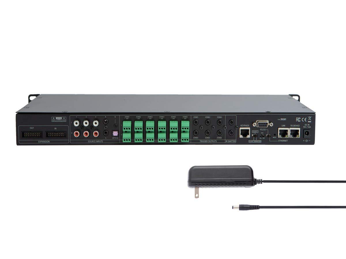
Audio Matrix
This unit is effectively an audio matrix. It takes 6 inputs, and can be controlled over the network to send those 6 inputs to any of it’s 6 outputs, with controllable volume for each output. Bonus points - it is rack-mountable so can fit in my home network rack! I only need four of the outputs for now, so there’s even room to grow.
This is the perfect unit to be the base of such a whole-home audio system, but it’s not capable of driving speakers directly - it needs an amplifier to actually produce sound. At first, this seemed fine - how expensive could 8 channels (4 outputs x 2 channels each for stereo) worth of rack-mount amplifiers be?
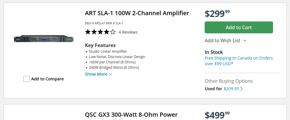
Oh.
Well, that puts a damper on this project. I started thinking of other alternatives, but most of them seemed terrible and poorly integrated. Eventually, when browsing DigiKey for an enclosure for an unrelated project, I found a CH-14401 rackmount “project box” / electronics enclosure
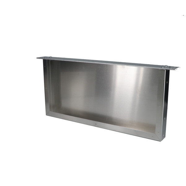
This is a reasonably-sized box for me to cram a power supply and a few circuit boards into. I started to plan out a project to design and build some amplifier PCBs and assemble them into this unit to give me the amplification channels I needed.
I have pretty extensive experience with low-speed digital design - I’ve designed and built more little circuit boards than I can count - but I avoid the analog domain out of mostly fear. I decided this was a good opportunity to tackle that hurdle and try to design as low-noise an amplifier as I possibly could.
I decided to build four copies of the same stereo-amplifier board to support modularity - if I blew up one of the boards, I could go and replace it with another one without too much cost. In retrospect, this was a poor decision - I should have built one stereo amplifier board to prove the circuit would work, then go back and design one board with four amplifiers on it There were way too many cables crammed in the enclosure to run (a lot of) power to four separate boards and have (high power) speaker output cables running around too.
A lot of research later, and I had designed a schematic to work off of:
The board features a TPA3116D2 class-D (switching) audio amplifier IC, along with supporting circuitry. Something novel I attempted to implement was a soft on/off circuit which would use an RC delay circuit to sequence the shutdown and mute lines of the amplifier to prevent the speaker outputs from making a loud “pop” sound when the board was enabled or disabled. This was my first attempt at “real” analog circuit design, and involved a lot of reading and re-reading old ECE textbooks and LTSPICE simulations:
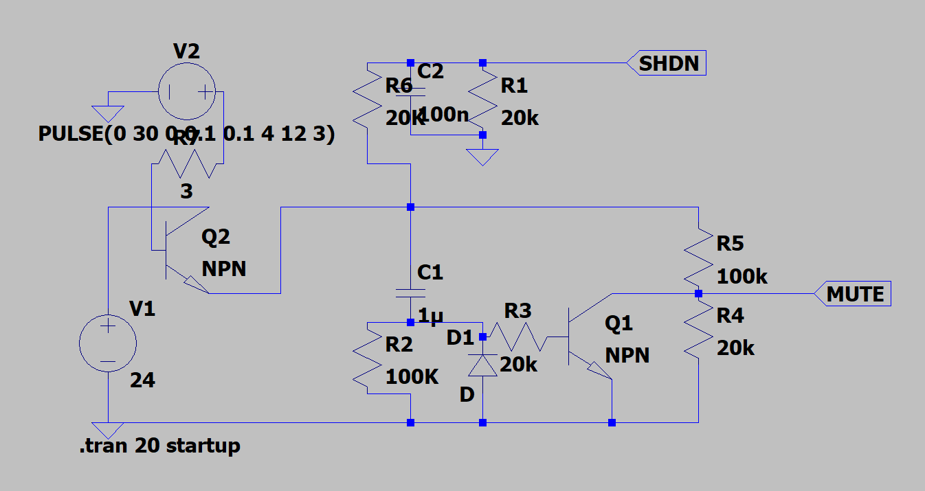
Simulating this stuff is a lifesaver
And after even more research about analog layout rules (especially when it comes to class-D amplifiers - things like minimizing loop length for the switching outputs and using film capacitors to reduce harmonic distortion at different audio frequencies), I had designed a board:
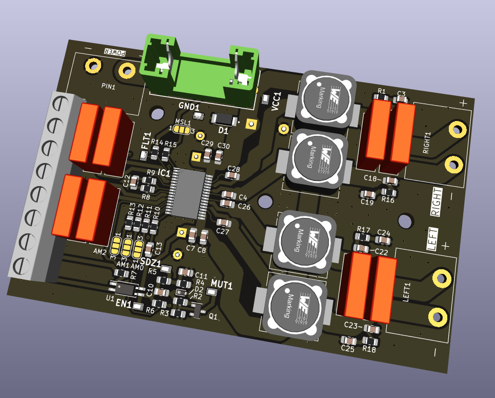
Something very satisfying about the giant film caps and inductors…
I sent the designs off to JLCPCB for manufacturinging, and less than a week later had a collection of very pretty black PCBs. After some assembly (wherin I wished for a pick and place machine to save me from an hour of using tweezers to place components…) I had finished boards, ready for a test-fit and a quick sound check!
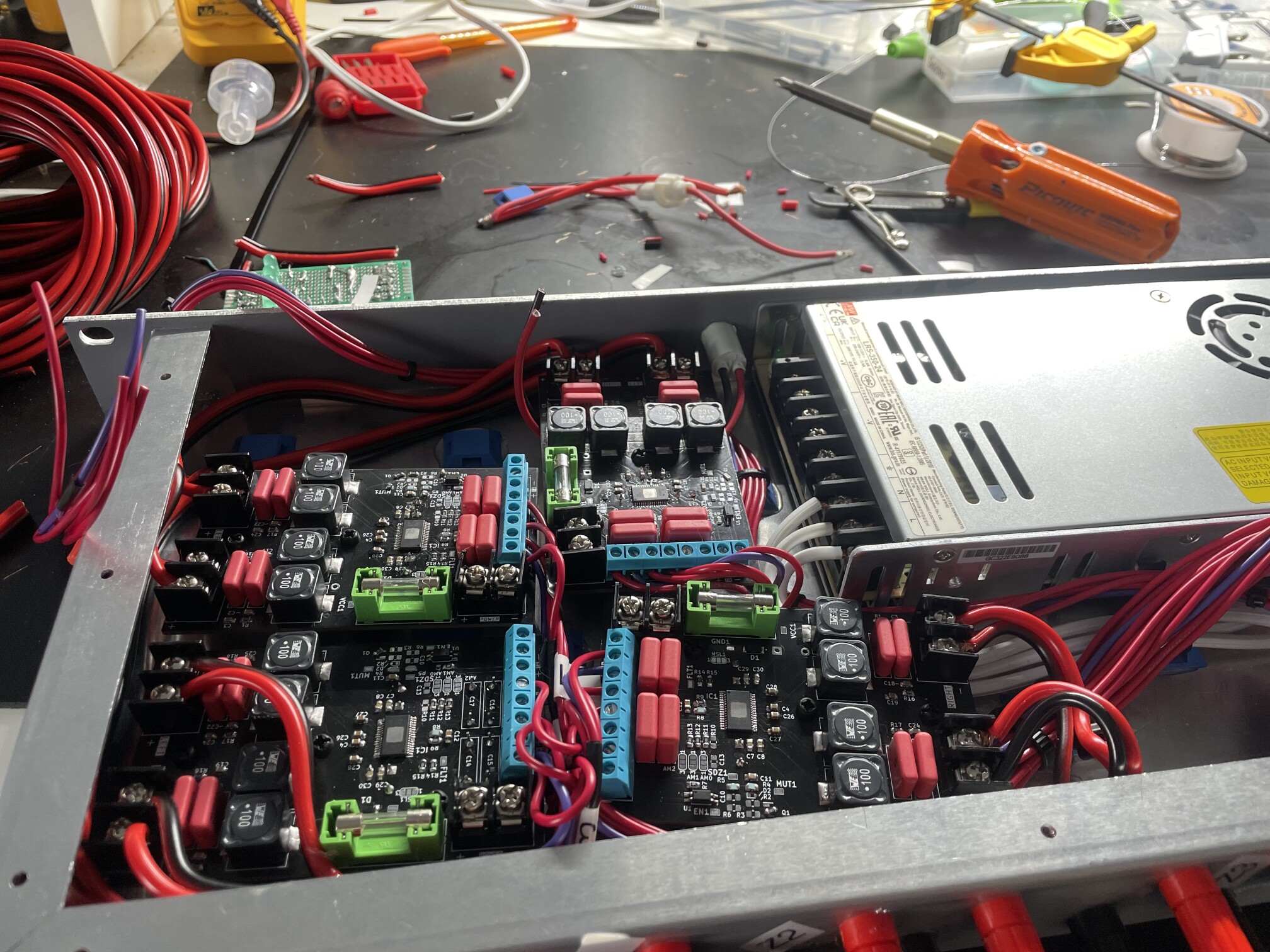
They fit! (mostly)
This was the point at which I realized I had made a mistake - I would have been far better off designing a single large board with four stereo amplifiers on it (or some kind of mezzanine/daughter-board arragement). Getting all the wiring and connectors in there was a huge pain!
But, then it was time to turn it on for the first time, and it sounded amazing. I was very happy with the result - zero audible “hissing” noise coming from the speakers, particularly when using the inputs in differential mode.
Alas, it was not all perfect - my original “creative” enable circuit to stage shutdown and mute had a fatal flaw - I had read and re-read the datasheet to make sure I got the polarity of the shutdown and mute signals right, but after all that I still managed to mess it up, and it didn’t work exactly right and I wound up hearing just pops, and no real audio… Luckily, I had planned for that particular mistake and was able to bodge a solution in place to directly drive the mute line from the enable line, and leave the amplifier always out of shutdown mode. This seemed to have little effect on power consumption anyways.
With the amplifier boards done, I could wrap things up. I prototyped a solution to rig up a fan to the enable inputs using some diodes and a reed relay:
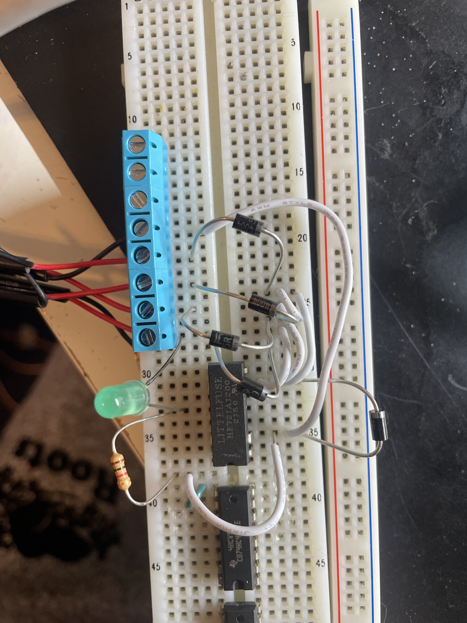
Screw-terminals that fit in a breadboard are a lifesaver for stranded wire.
then soldered it to some perf board and installed the fan and cut some speed-holes to promote airflow:
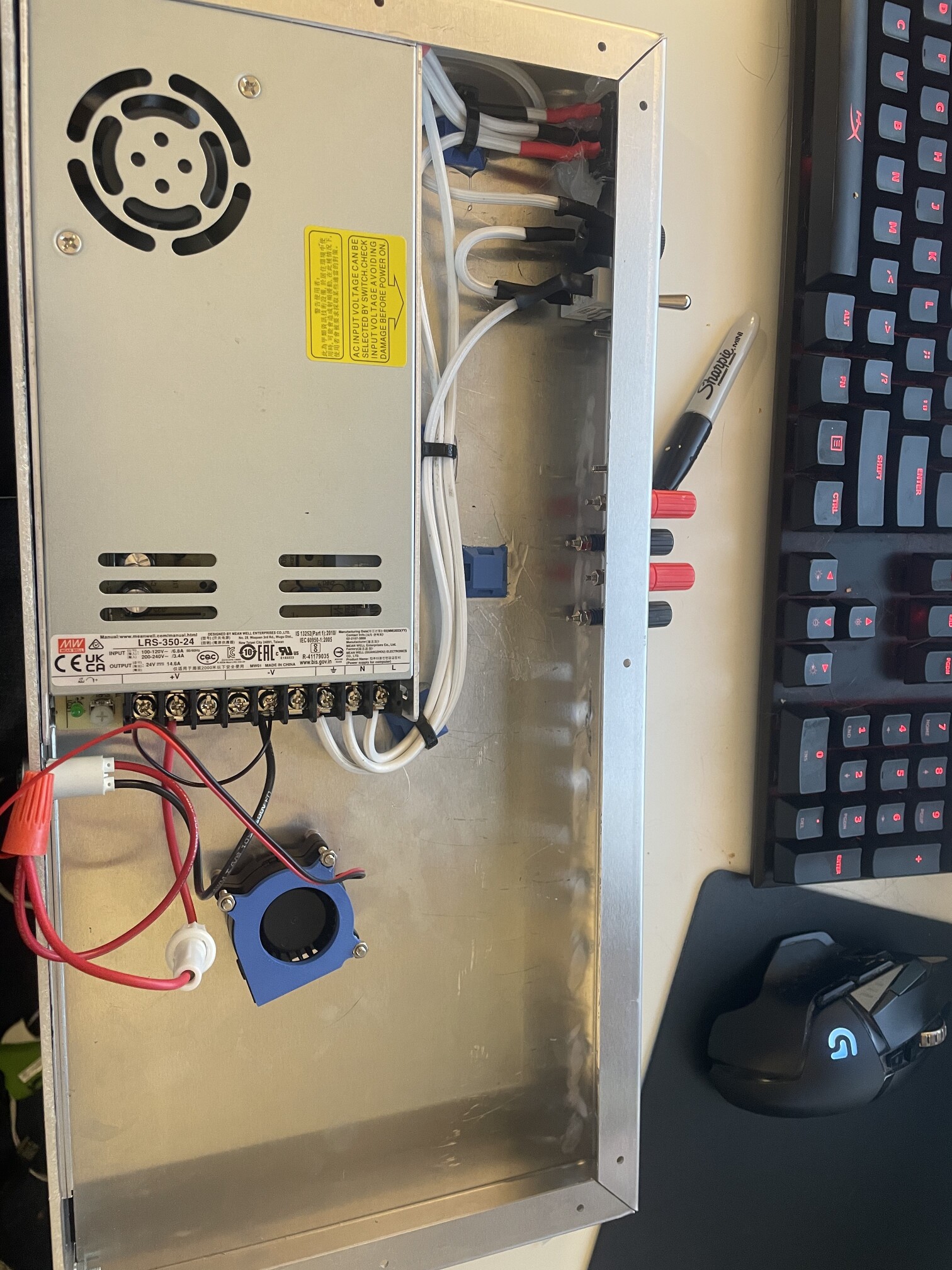
These amps get a bit toasty when running full bore…
With that wrapped up, I installed it in the rack, powered it up, and enjoyed music all throughout the house!
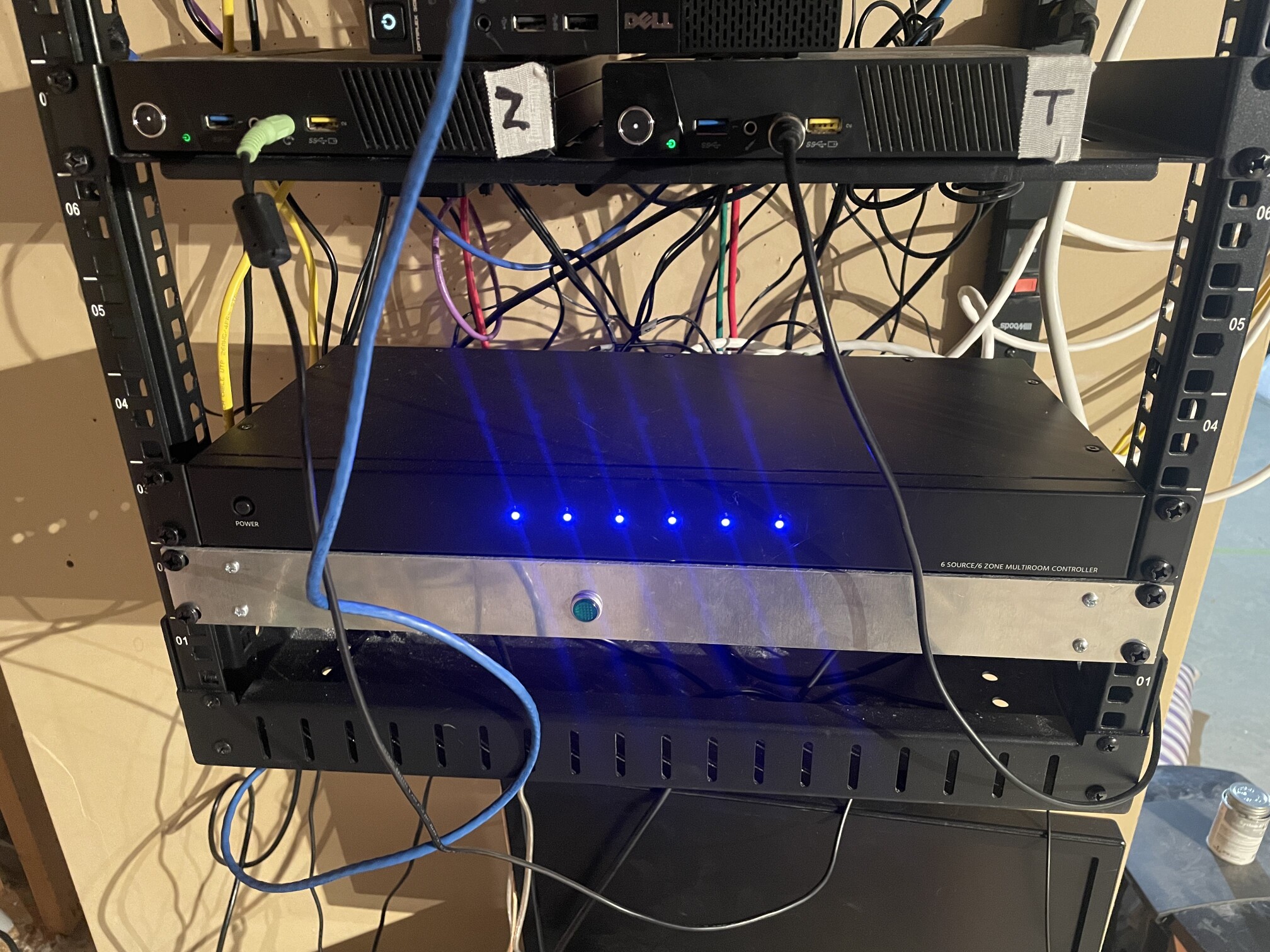
It’s alive!
At this point, I thought I was done, but I couldn’t leave well enough alone. Remember how I said that I only used four of the six pre-amp outputs? Well, now I wanted to use the other two. I have a couple locations like our living room which already have speakers and amplifiers in them, and are really annoying to pull new cable to. But I already have some Ethernet there… So what if I could get low-latency audio over that Ethernet network?
I’ve recently been enjoying these esp-poe-iso ESP32 development boards - they have precious few I/O pins, but it’s still a Power-Over-Ethernet ESP32 in a nice tiny package, with a built in PHY so the ESP32 can communicate over Ethernet as well.
I drew up a couple more schematics and boards - one is an audio analog-to-digital converter that takes a differential audio signal and turns it into i2s digital sound data for the ESP32. The other is a digital-to-analog converter that converts i2s digial audio from the ESP32 to line-level audio output perfect for feeding into an amplifier:
This was a good opportunity to learn how to mix digital and analog circuit domains! The ESP32 module has a 3v3 rail which is tempting to use for the ADC and DAC chips, but some quick probing shows that the power is far from clean, especially as the ESP32 starts doing work. Even with the pretty good PSRR of the ADC and DAC chips, I didn’t want to risk it, so I included a low-noise linear LDO to convert the (cleaner) 5V rail to an analog-3v3 rail for the audio chips.
Layout was also a bit fun here, keeping the rapidly oscillating i2s lines away from the audio domain, but before long I had two boards:
ADC board! DAC board!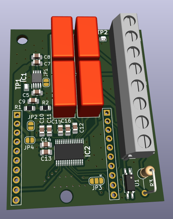
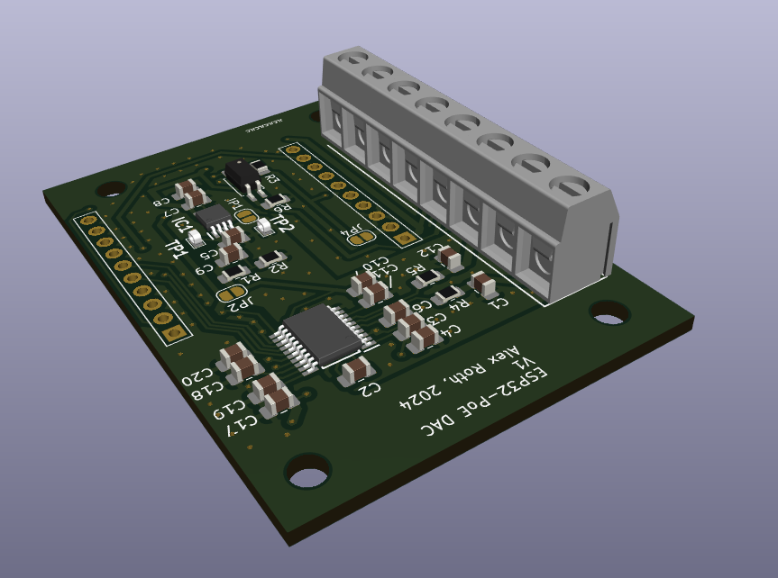
One more quick-turnaround from JLCPCB and a little bit of hand-SMD assembly (I’m getting ok at it…), I had some completed boards:
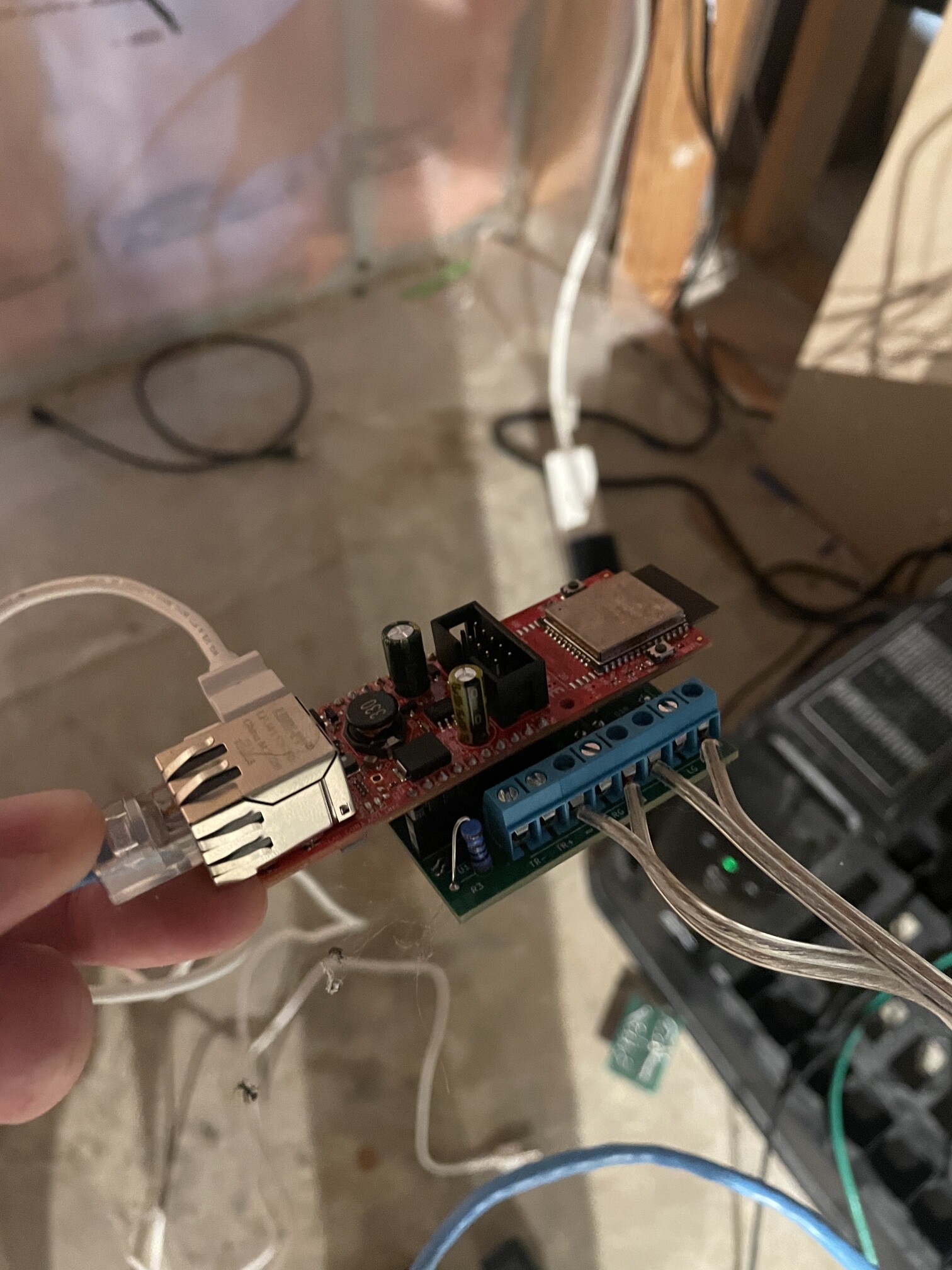
ADC board hooked up - note differential audio inputs with no ground.
I brought up the ADC board first - writing some code using Espressif’s esp-idf to configure the ADC over i2c, then start receiving 16-bit stereo audio samples over i2s. It then packaged those samples up as RTP packets before sending them out to the network over multicast for anything else to receive. I was able to use ffmpeg on a Linux host to receive this audio and play it back to prove it was working. I needed a few tweaks to the endianness of the bytes and such, but eventually I had remarkably clean audio coming in from the ADC board! I had managed to avoid the dreaded “hiss” and low-noise floor again.
Next, I wrote firmware to do the exact inverse for the DAC board - take samples over multicast RTP, turn them into i2s buffers, and play them using the DAC. I was less lucky with this board - there was a noticable “hiss” in the background of the audio coming out of the board even when being fed constant “zero” samples. Can’t win them all, and I have some theories as to what might be going on related to the way I laid out the board.
The ADC board was working great, and in an end-to-end test it added almost imperceptable latency to the audio vs. speakers running from the amplifier boards - good enough that you don’t wind up with weird beat frequencies or an “echo”. The one sad thing was the “hissing” DAC.
Then I looked real close at the amplifier I was using in the living room and found the SPDIF optical input:
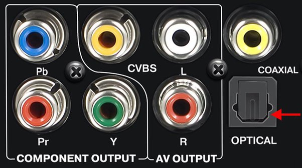
Digital input!
If there was ever a path to noise-free audio, a digital audio input is probably it! After some research, I found that it was possible to configure the ESP32’s i2s peripheral to produce a bitstream that was acceptable for SPDIF. While technically you need an LED with a very specific wavelength to drive this port, I figured it was worth a shot with a 3D-printed adapter and random red LED I had sitting around:
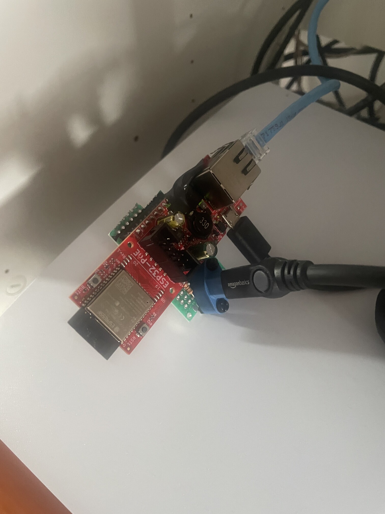
Janky and jury-rigged, but will it work?
After some fiddling with the code and bitrate settings, the amplifier indicated it was receiving valid PCM data! I fired up the ADC board and started playing something, and it came through the amplifier crystal clear. The latency is a tiny bit worse than the DAC board was (you can hear the latency if you really try), but the audio quality is worth the tradeoff to me.
Overall, this was a great learning opportunity to dip into the world of analog circuit design - I learned a ton about the tools and resources available for this sort of project and am super happy with the overall outcome.