E-Paper Display
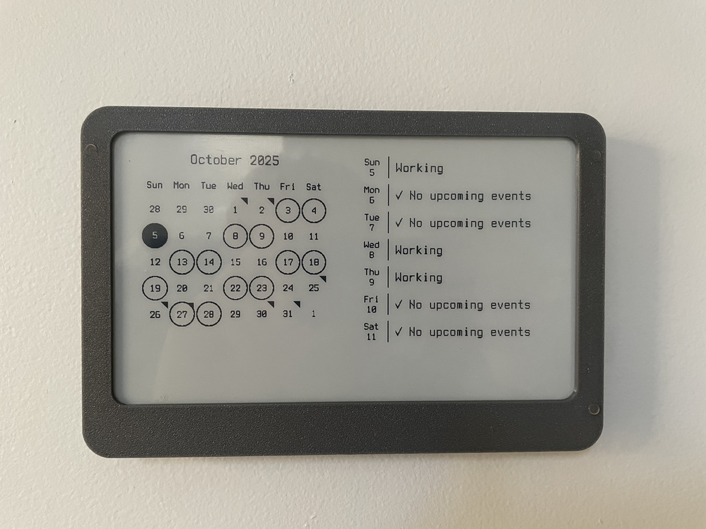
A few months ago I found the trmnl project - a network-connected e-ink display with the intention of providing “passive information” - put it up on the wall, and it cycles every few hours to show different bits of information - a calendar, upcoming weather, news headlines, etc.
The concept was interesting to me - a while ago I built this network-connected e-ink display, along with a small server component to render images for the display. At the time, I just used it for a calendar - it was handy to see which shifts my wife was working and upcoming family events at a glance. The implementation was pretty crude, and it required wall power.
I was inspired to build something better - a battery-powered, wireless e-ink passive display. But I had a few goals in mind beyond what trmnl provides:
- Support for different sized (and multi-color!) displays - I want to be able to use smaller 2.9 inch or 3.5 inch displays for some locations, and larger 7.5 (or more)! displays in others.
- Battery life of at least 6 months (ideally over a year!)
- Avoid lithium-ion batteries (I just don’t trust myself to design a truly safe battery system, and ni-mh and other chemistries are much harder to go up in flames)
- Wireless communications with an IP network (either WiFi or Thread-based) for display updates - but not dependent on a phone or similar to write display data over NFC.
Some research into e-paper vendors led me to Good-Display and a little later, Pervasive Displays. There seems to be some degree of standadization for these SPI-driven displays - almost all of them use the same 24-pin FPC connector with the same pinout and roughly equivalent “driver” circuit. I have yet to find a display in the 2 - 10 inch range that doesn’t use this pinout… but definitely use caution and read pinouts!
The “driver” circuit for these displays is actually just a simple boost converter supplying a fairly sizable positive and negative voltage, used for polarizing the display elements to change the color displayed. There are a few references for this circuit - the Waveshare e-paper “HATs” have published schematics and good-display has a short document. This is what I came up with:
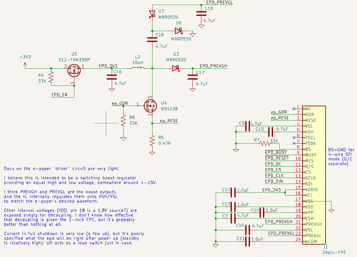
Load switch & boost converter circuit
The mirocontroller selection process was fairly short - I knew already I wanted to use a Nordic microcontroller to get some experience with this popular family. I quickly settled on their new nRF54L15 series - the improved power consumption made it attractive, even if there were fewer resources available about them.
I debated for quite a while on if I should use a chip-down approach and lay out my own RF circuitry to a chip antenna, or if I should just use an off-the-shelf module with integrated antenna. In the end - I didn’t have the right equipment to perform antenna matching and testing for radiated emissions, and I didn’t really want to put an intentional radiator into service without any testing first. At some point I want to revisit this and try to redesign it without the module.
I also selected the nPM2100 as the boost converter for the circuit, due to it’s low quiescent power while in power-down mode (150nA!) even with a wake-up timer running. At one point, I had a design which ran directly from a coin cell or two AAs in series, but the e-paper display seemed to mis-behave a bit at 3V, and I wanted to wring as much lifetime out of the batteries as possible. By using a boost converter, we can still power the circuit from a single battery discharged down to 0.8V.
I drew up a relatively simple schematic connecting everything together and started laying out the board. With a 4-layer stackup to improve signal integrity and EMI, I was able to cram everything into a 63mm by 20mm board:
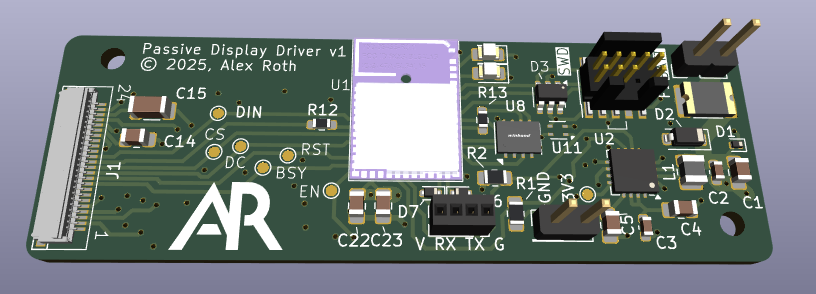
It’s smaller than it looks!
I probably could have made things even more compact, but I wanted to keep the board “easy” to hand-assemble (which limited me to mostly 0805 passives), and I didn’t want to pay the extra cost for a 6-layer board (which would have left more free space on the top layer to squeeze the boost circuit in a little tighter).
After a week or so, I got boards back from JLCPCB (as quick and high-quality as ever!) and started assembly.
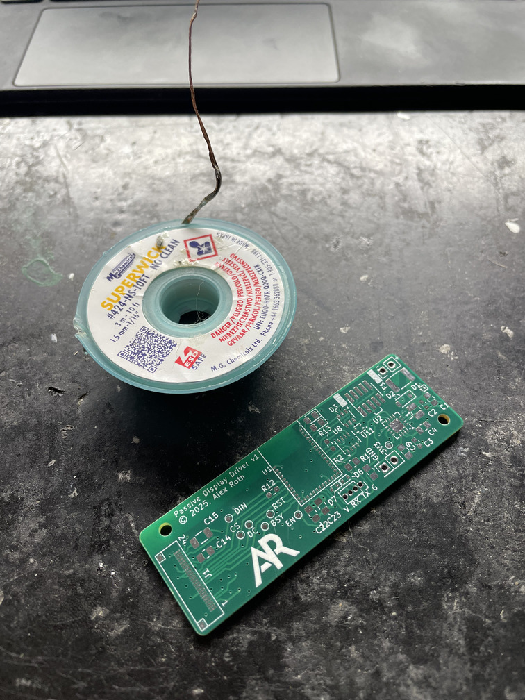
Solder wick reel for size! These are really tiny.
The nRF54L15 module I chose (BL54L15) is an LGA “package” at 0.8mm pitch. It was not trivial to hand-solder 🙂. The method I wound up using was to tin all of the pads on the module first (with lots of flux), place the module as close to the correct location as possible, pre-heat the board, and use hot air until the module visibly re-flowed into place, flush with the board.
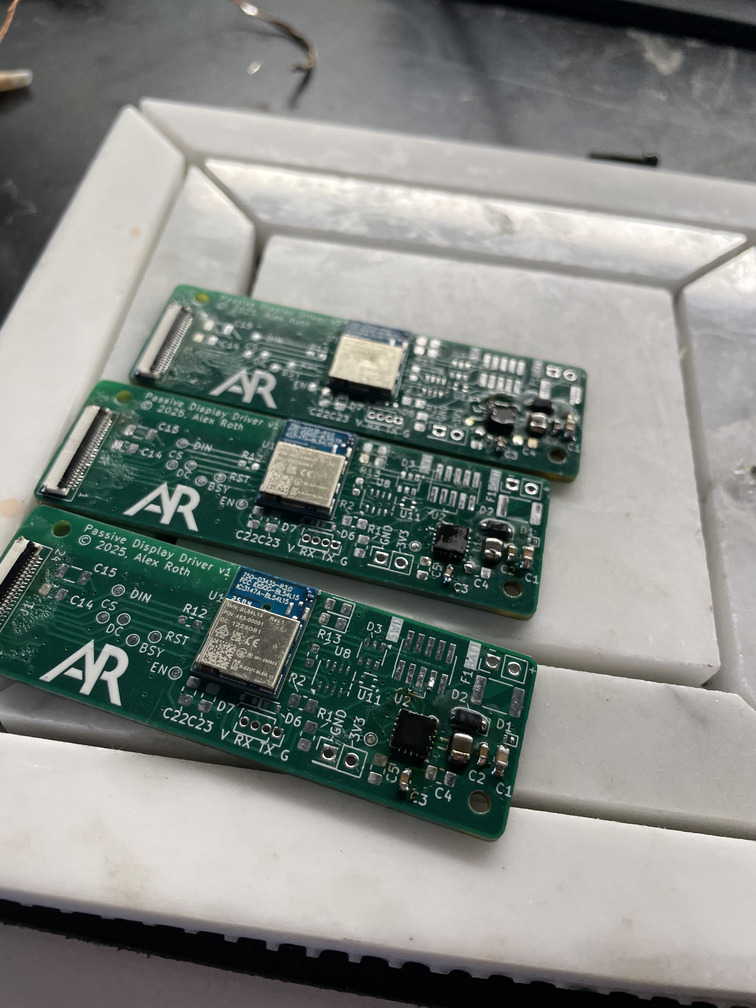
3 boards with BL54L15 modules and nPM2100 soldered in place
In retrospect, I should have (a) ordered a stencil and hot-air reflowed the entire board at once, and (b) drawn a footprint for the module where the pad extended past the outside of the module. This would have made it easier to check for short circuits between each pad.
Bring-up of the board went fairly well - it was my first time using Zephyr. Overall I am impresed with the quality of code and the number of off-the-shelf drivers that mostly “just work”. When things go wrong (or to figure out what magic config options you need to set) you often have to wade through a lot of boilerplate, but overall I didn’t need to patch anything in order to make my code work.
The boards connect to my home IP network over the Thread protocol. I configured the OpenThread Border Router to act as a gateway for the displays. Once they had network access, I implemented a straightforward over-the-air update scheme which downloads update files using CoAP.
Image files were next. I implemented a server which provded binary bitmap images using CoAP which the processor could simply write directly to the display. The download process took an unfortunate amount of time - 48 kilobytes of raw image data, which took 45-60 seconds over a low-quality Thread link. This was too long to keep the radio and display active and still meet our battery goals. I was able to reduce this to 15 seconds or less by employing heatshrink compression to the bitmaps - large areas of the display are the same colour, so this compression can shrink images down to 3 kilobytes or less. I used a Nordic Power Profiler Kit II to compare total energy use between the two protocols, and having the radio (and CPU) on for a shorter period of time more than made up for the CPU working a little bit harder. The heatshrink library is particularly well suited for embedded use cases, as it doesn’t require a large output buffer - you can pull bytes out one at a time if required.
Speaking of power consumption - I was very happy with the end results in both sleep mode:
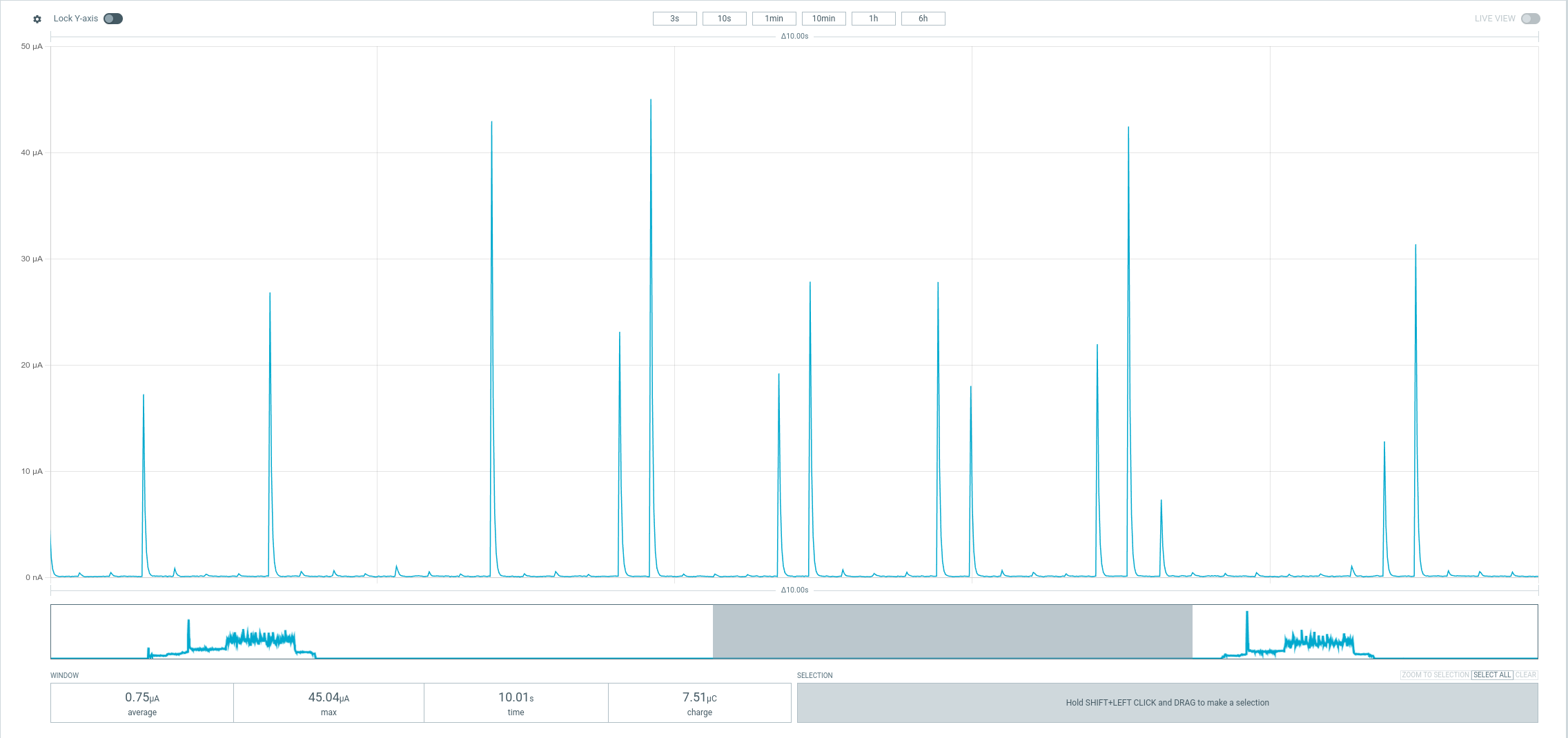
Power consumption in sleep mode
and in a refresh cycle:
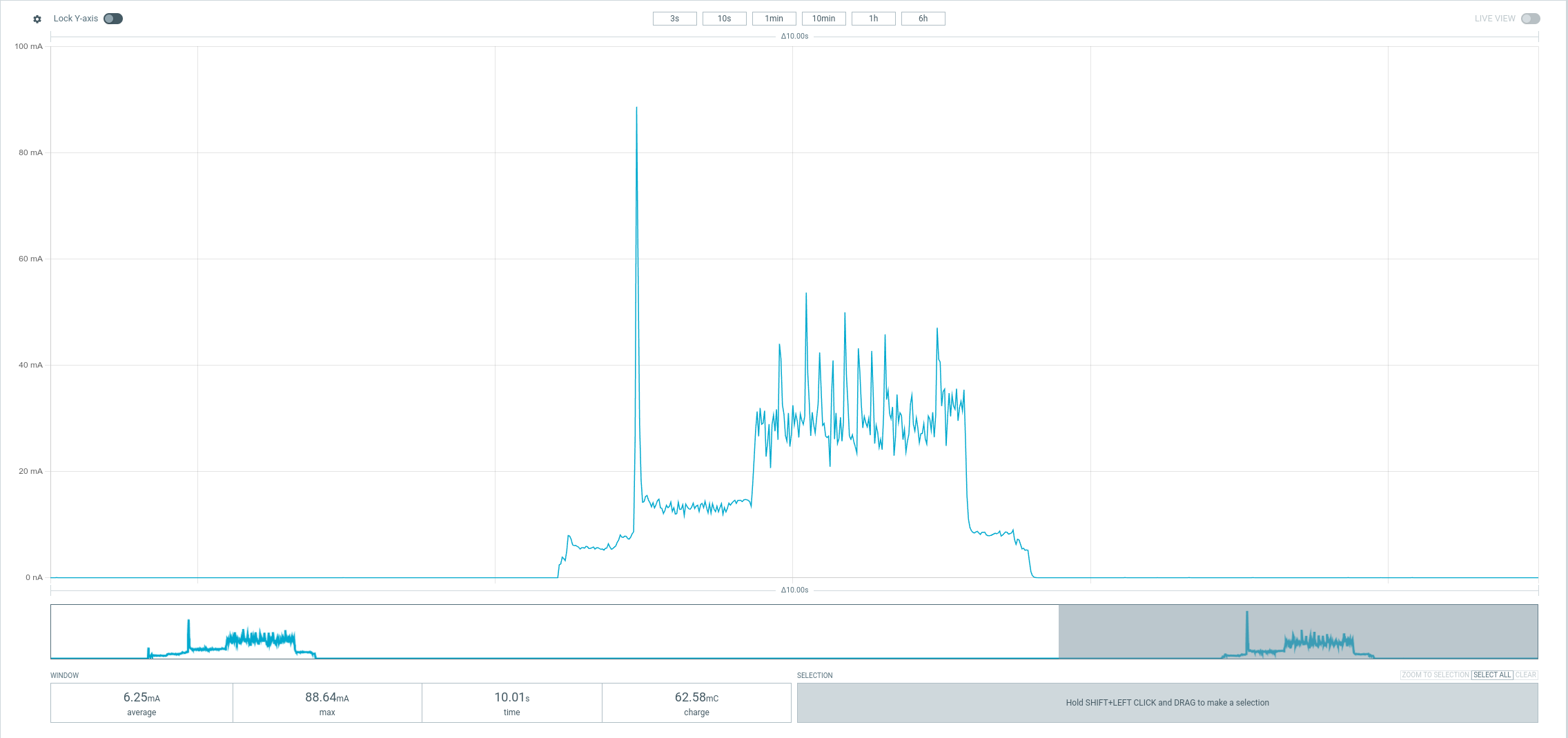
Power consumption for a refresh cycle
Comparing with the TRMNL firmware (power consumption figures here), my displays use a tiny fraction of the power in sleep mode and in refresh compared with TRMNL. The improvement in sleep mode is primarily because of the PMIC I chose, which supports an incredibly low-power sleep mode where it completely cuts power to everything except a very simple timer - only waking up the system again when the timer expires. The improvement during refresh is primarily due to the lower power requirements of the nRF54L15 using Thread vs. an ESP32 using WiFi. Note that I ran my tests at a 1.3V input, TRMNL used a voltage of ~3.9V.
I’m expecting the displays to last for the better part of a year on a single Eneloop rechargable AA battery, but that has yet to be fully tested at this point.
To wrap things up, I modelled up a case for the whole system which could be wall-mounted. For the first time, I modelled in a battery holder directly. I ordered battery contacts from DigiKey and modelled them into the case directly. It required some tweaking for tolerances, but the end result was nice and clean. I will do this in the future when I need to use AA or AAA or even button cells - it’s much more flexible than using a battery holder on the PCB itself.
Front panel of the display, 7.5 inch screen
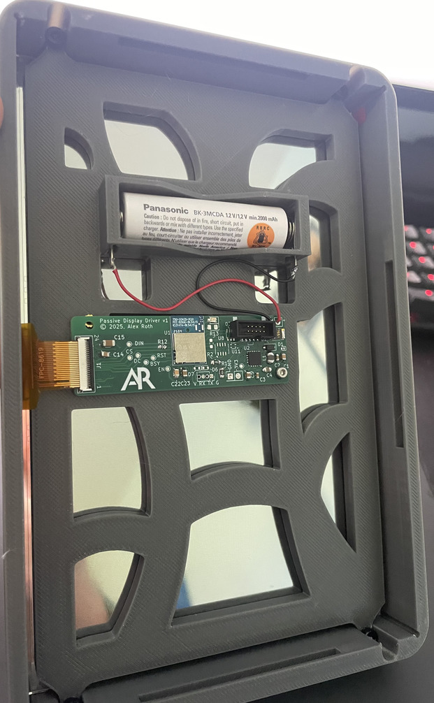
Inside/back of the display, 7.5 inch screen
I also made a second version of the case for 3.5 inch displays:
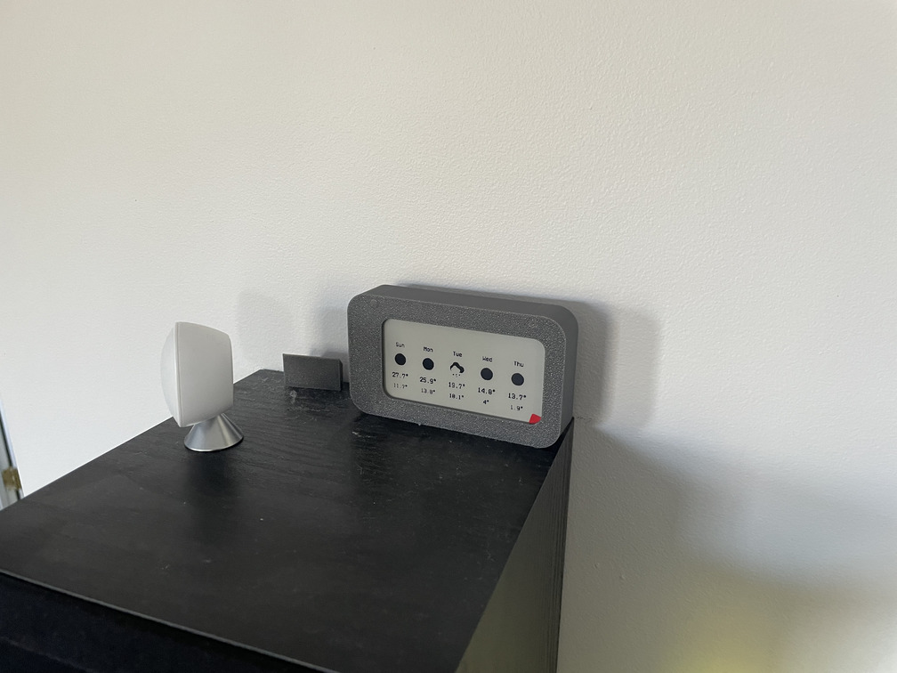
Front panel of the display, 3.5 inch screen
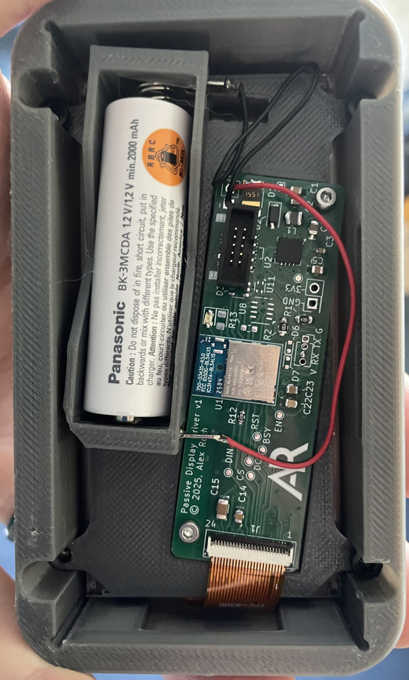
Inside/back of the display, 3.5 inch screen
I’m happy with the hardware at this point - but I have a lot of work to do on the software to render better-looking and more useful dashboards. My first pass is simply Home Assistant dashboards rendered into an image and pushed to the screen - but font rendering in particular is rough.
Source code and hardware for this project can be found here.