Custom Firmware for Alarm Controller
The house I live in came with some old, but functioning alarm sensors. Unfortunately, there was no control panel for the alarm system - it had seemingly failed and been removed quite some time before.
I found this Eyez-On Envisalink UNO board for sale. It was from a manufacturer well known for integrating well with alarm systems, and had been a player in the industry for a long time. Using their supposedly “stand-alone” system made sense to me.
There are definitely other options out there, like the various products from Konnected.io. I wasn’t a huge fan of the Konnected products though, both because the non-“pro” versions rely on WiFi to connect the alarm system to another management system (!), and a complete lack of support for end-of-line resistors.
End-of-line resistors are worth a little sidebar here - in an alarm system, you normally wire everything “normally closed” - so when a sensor activates, it opens the circuit. This lets you make sure that everything is fine, and the wire hasn’t been cut - after all, if it was cut, you would see an open loop, and thus think a sensor had tripped. But what if the circuit has a short somewhere along the line, connecting the two wires together? You can’t tell the difference between a short circuit, and “all good”. That’s where an end-of-line resistor comes in.
By placing a resistor at the “end of the line”, you can have the control board measure the resistance of each alarm circuit. Since the end-of-line resistance is a known value and will stay relatively constant over time, you can detect a problem if the resistance ever changes significantly.
This is a really nice feature - it lets you have confidence that the circuit is operating correctly and hasn’t been tampered with. Konnected doesn’t support that, but the EyezOn boards do!
This interface board was going to be used to bring the various sensors into Home Assistant, where the actual alarm logic would live. It was pretty important that the interface support some protocol that Home Assistant also spoke - luckily, because EyezOn has been in the business for a long time, HomeAssistant has support for these boards! They speak a documented protocol that can be used to query state, get updates on sensor state, and more. From everything I had read, it would “just work”, so I bought it and got it installed.
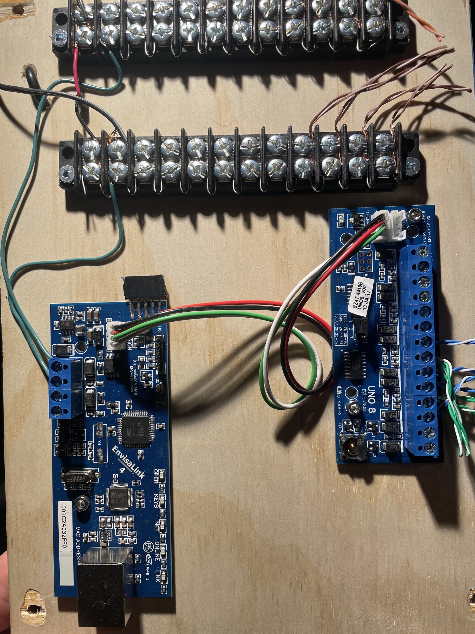
Installed!
Turns out, I had opened a huge can of worms. EyezOn, with their “stand alone” system, does not support any local control/query protocol, unlike their “attached” systems that rely on connecting to DSC or Honeywell alarm control panels. There is no documentation to suggest that it wouldn’t work, and so I asked on the forums to better understand what might be going on:
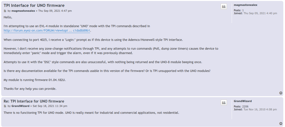
An attempt to reach out
Oh. Alright then. So I’ve just purchased a brick. Well. If it’s a brick anyway, I’m not going to hurt anything by trying to see how this thing ticks, am I?
I stared by pulling the various stickers off the board and looking up part numbers. To my surprise, the main microcontroller was an ATXMega - a microcontroller family I knew quite well. At that point, I had an idea… What are the chances they left the programming port available to access? I started mapping the pins of the microcontroller, figuring out where they landed. Much to my benefit, the programming pins were broken out on what seemed to be a dedicated programming header! I hooked up my trusty Atmel ICE debugger, fired up avrdude, and…
avrdude: AVR device initialized and ready to accept instructions

Reading | ################################################## | 100% 0.00s

avrdude: Device signature = 0x1e9647 (probably x64d4)
Sweet! They didn’t disable the programming interface at the factory. The lock-bits are set so that I can’t read out the firmware, which is fair and totally fine. But I can replace the firmware with my own image, if I can reverse-engineer enough of the board.
I started digging in deeper - hooking up my logic analyzer to the communications interface between the main board and the UNO8 expansion board. I quickly found out that it’s a simple I2C interface, with a few protocol quirks:
0x00 -> ID request. Returns a 3 byte board identifier of some description. Mine is "0x41 0x4D 0x43"
0x10 -> ADC value request. Returns 8 bytes indicating the current "value" for each of the 8 channels.
        I don't know how this translates to voltage/current, but I do know that by watching it you can
        figure out if it's open circuit, closed circuit, or has an EOL resistor of various values.
After a bit more playing, I wanted to be really sure that I had things right before I re-flashed the chip. I connected the UNO8 board to a random Arduino lying around, and wrote some trivial code to query the sensor state over I2C. And it worked!
The last step before re-flashing the thing was to do a full pin mapping to make sure there wasn’t some hardware watchdog or something else that was going to ruin my day if I didn’t know how to talk to it. I did a full pin-mapping of all of the chips on the board to find out what everything was and how it was pinned.
Then, it was time for the moment of truth - I wrote a trivial “hello world” that wrote data out to the serial port, built it, and flashed it to the board. I hooked up my logic analyzer to capture the serial output, and..
hello world
Wild success!
A bit of simple stuff later, and I had the microcontroller conversing with the UNO-8 board, getting all the sensor states as analog values (to detect the end-of-line resistors and confirm the line hadn’t been tampered with). There was still one giant hole in the functionality… that Ethernet port.
Ethernet communications happened over this AX88796 chip. There was some rough auto-translated documentation which explained little more than how to get the chip out of a reset state, and it really was just a raw SPI Ethernet MAC - unlike the W5500 chips I’d played around with before, there were no helpers for the upper layers of the IP stack. This was a bit of a problem. Most of the IP stacks out there are gigantic, and a bit of a pain to port.
But how complicated is IP really?
I decided to do something crazy, and just write my own UDP/IP stack. I didn’t need any of that TCP nonsense, after all. It turns out that it’s remarkably simple to implement the lower-level protocols like ARP and ICMP, and really not that much more to implement UDP. I was able to implement all of this just following RFCs, testing for inter-compatibility using Wireshark and a Linux host. Before too long…
$ ping 10.102.40.20
PING 10.102.40.20 (10.102.40.20) 56(84) bytes of data.
64 bytes from 10.102.40.20: icmp_seq=1 ttl=129 time=0.251 ms
64 bytes from 10.102.40.20: icmp_seq=2 ttl=129 time=0.180 ms
64 bytes from 10.102.40.20: icmp_seq=3 ttl=129 time=0.555 ms
^C
--- 10.102.40.20 ping statistics ---
3 packets transmitted, 3 received, 0% packet loss, time 2029ms
rtt min/avg/max/mdev = 0.180/0.328/0.555/0.162 ms
(side note: I was happy to eventually get ping times fairly low - at first I was clocking the SPI bus very conservatively, which led to super slow response time for packets - the time to transfer the packet to/from the MAC was dominating the processing time! Once I figured that out, I was able to clock the SPI bus closer to 10MHz and reached these response times.)
The code for all this nonsense is here. It is gross, but it was also thrown together in a couple weeknights. I’ve since expanded it with support for multicast groups (including IGMP), but I have some more cleanup to do before publishing that.
In order to meet my original goals here, I needed a way to query this device from a Linux host, and ideally some sort of publish/subscribe system to keep updated with current state. The Constrained Application Protocol (CoAP) was a great fit here, and the RFCs clearly explain how the protocol is implemented. It was easy to slot this on top of my netstack, and then I could use standard coap tools from Linux to interact with the device. I wired up a few configuration endpoints and wrote a tiny script to receive CoAP POSTs and transmit them as MQTT messages.
With that working, the project was complete! I could use standard 12V alarm sensors with Home Assistant entirely locally, with super reliable hardware complete with end-of-line resistor support. I am very happy with the end result, and over the past couple of years of service, I haven’t run into so much as a dropped packet.