Garage Door Hackery
I’ve been on a quest, over the past few years, to automate the places I live. I don’t see much point in going full tech-YouTuber about it, and making you use your phone for everything in a house - that’s not making your life simpler. There definitely is a lot of value in the small stuff. Lights all turning off when you leave the house. Garage doors that alert you when you left them up. Combining all the pieces of gear that make up a home theater into one interface. Things that you can interact with in “normal ways”, but have an air of intelligence added to give you less to think about day-to-day.
I’m a strong proponent of “local-only” home automation. Your house should not depend on the Internet. All of my equipment runs through Home Assistant, providing a central place to control things and set up automations. Everything is local-only - Lutron Caseta switches, Hue light bulbs, Yamaha AV receiver (local API!), and an un-countable number of tiny custom ESP8266 projects that talk over MQTT.
Except one thing. That one thing is Chamberlain’s MyQ garage door control, which I use with an RJ020 opener. That runs through the cloud. It was disappointing, but it “worked” better than most IoT crud that you could buy. The app was “fine”. It tied into Home Assistant to power automations. It generally didn’t require thought, which is all I can ask for.
I learned my lesson one November morning when Chamberlain decided to unilaterally block access for customers using their API.
Time to find a way to make it entirely locally controlled.
The Home Assistant project recommended ratgdo, which looks like a pretty neat solution to the problem. I don’t like that the hardware isn’t open-source (no schematics or documentation of protocols have been released by the author), but at least the code was released (it’s since been removed from GitHub, seemingly. It might have been moved to some other repo? Not linking to it makes it seem intentional though.) Unfortunately, shipping to Canada was prohibitively expensive, and there’s currently at least a month of lead time before orders ship out. Something felt off about that whole situation, so I decided to do my own thing.
I’ve got a pile of ESP WiFi modules, a bunch of miscillaneous electronic components, and a free evening. Let’s see what we can do.
My goal for this project is simple - I want the ability to read the state of the door. Up or down. That’s it. It would be a nice bonus to be able to expand the project to open/close the door in the future, but that’s not all that important to me.
Could I have used a simple Z-Wave tilt sensor or magnetic closure sensor? Yeah. Probably. But where’s the fun reverse-engineering in that? I can’t say I’ve ever built something just because it seemed easy.
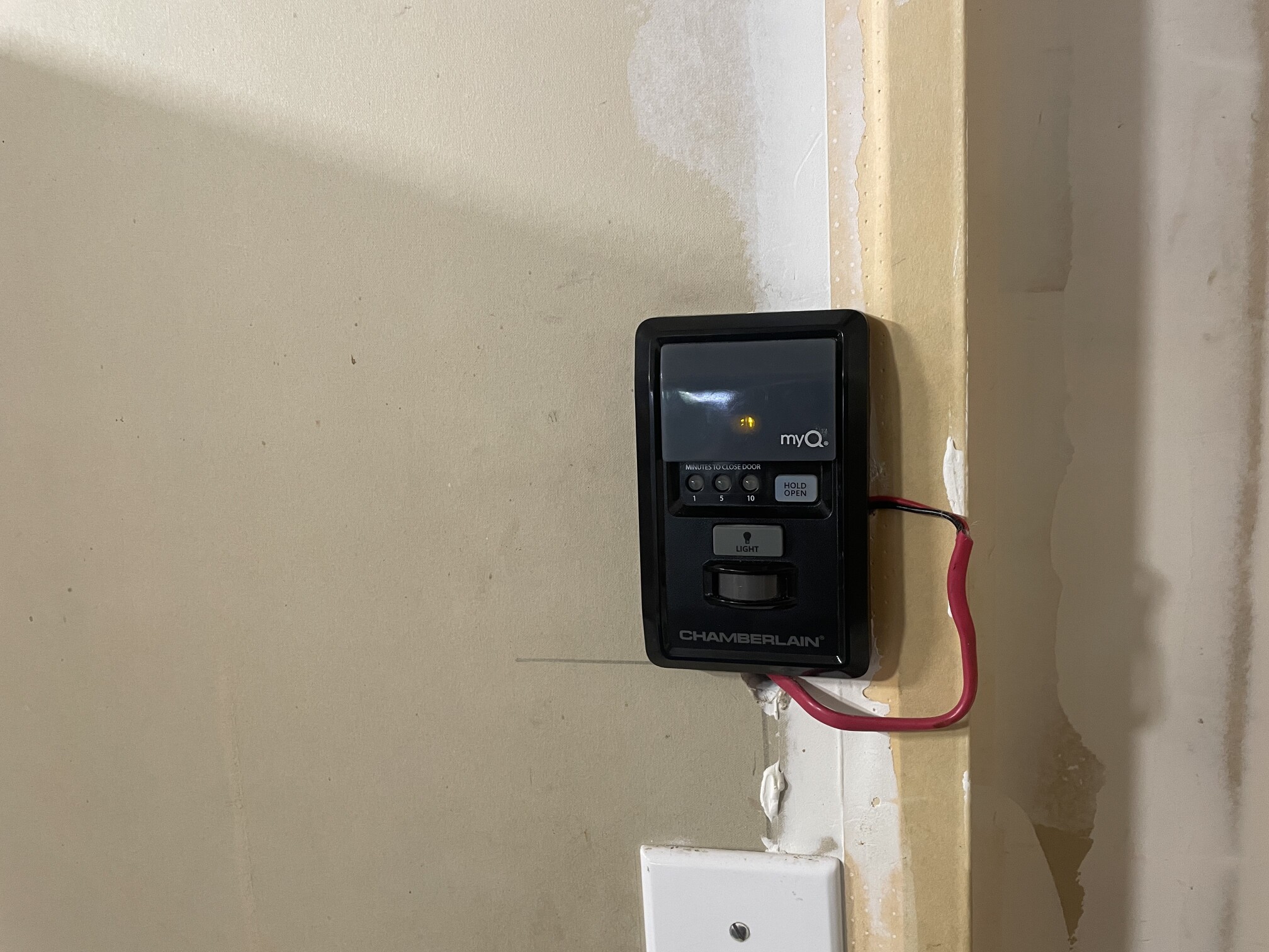
Controller, with wireless capabilities and motion!
This is the button that controls the garage door. It has an awful lot of functionality for something that just has two wires going back to the garage door opener, including a motion sensor, button to control the lights, and some crazy time-to-close functionality that I don’t care about.
I started in the place that felt intuitive - attaching a logic analyzer on the two wires. Enough years of reverse engineering have taught me that the majority of engineers building something go for simple and stable. Chances are the person who designed this didn’t build a wire protocol completely from scratch. I ran a capture, opening and closing the door a few times, and out popped this waveform:
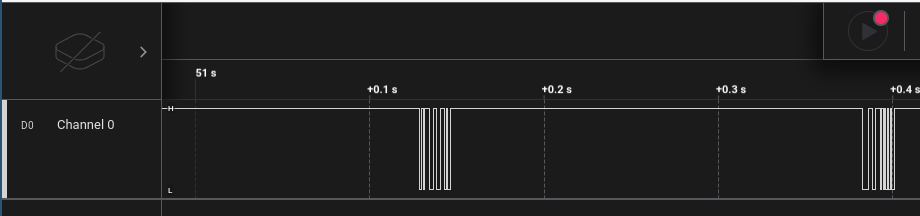
First capture attempt
That’s interesting. The signal seems to idle at 12V, and occasionally is used for data transfer. Presumably the wall opener gets power for it’s microcontroller from the bus when it’s high, and just has some built-in capacitors to ride out the periods of data transfer.
Quickly inspecting the signal, I found several transitions that lasted right around 840uS. Assuming this was one bit of data, that’s about 1200 bits per second. This might be some kind of Manchester encoding scheme, or some riff on Dallas’ OneWire bus. Or maybe something home-grown. Just for fun, I started trying different decoders within Salae’s Logic software, with bit rates around 1200 baud.
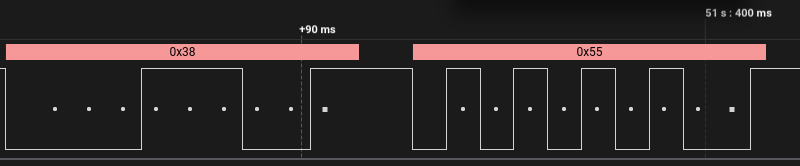
Serial data!
Or it’s just standard UART-style async serial. That was easy. This system seems to operate as a 1200 baud async serial bus, with even pairity, 8 data bits, and 1 stop bit. The fact that all of the bytes I captured had pairity check out leads me to believe this is either the correct decoding method, or a crazy fluke.
Now that the encoding was understood, I could start working on the harder part - interpreting this flood of bytes.
Approximately every 200ms, two bytes are transmitted onto the wire, in messages like 0x3855, 0x3A5C 0x3900 and then repeating over again. At this point, I don’t know much about this data. It might be coming from the opener, or from the button. It might be state updates, or just periodic handshakes to confirm the wire is intact. My usual style of reverse engineering is “perturb and observe” - make a small change, and see what changes in what I’m observing. When I started, the garage door was off, and the light was on.
I pressed the button to open the door, and noticed some immediate changes in the data stream:
- One “packet” of just one 0x30 byte was sent.
- One “packet” of
0x3131was sent. - While the door was in motion, the periodic messages changed to
0x3801,0x3A5C,0x3900. - When the door was fully up, the periodic messages became
0x3802,0x3A5C,0x3900.
Well that was fun. It sure appears that door status is being communicated on this bus, not just requests to raise or lower the door. Otherwise, the data stream wouldn’t react to the state of the door.
What if we turn the light off and back on using the door remote?
- When turning the light off, one “packet” of
0x3333is observed - Periodic messages change to
0x3802,0x3A58,0x3900with the light off. - When turning the light back on, one packet of
0x3131is observed. - Periodic messages return to
0x3802,0x3A5C,0x3900.
Okay. Sure seems like that first “packet” relates to door state, and the second “packet” relates to light state.
Let’s confirm our hypotheis and put the door down again:
- One “packet” of
0x30was sent - While the door is closing, periodic messages change to
0x3804,0x3A5C,0x3900 - When the door is closed, periodic messages change to
0x3855,0x3A5C,0x3900 - When the light turns off due to inactivity, periodic messages change to
0x3855,0x3A58,0x3900
I don’t know about you, but I think I see a pattern emerging. I still don’t understand the button inputs (the “one byte” or “repeated byte” packets), but the periodic messages are certainly status updates.
Based on a bit more observation, I think we can decode these status updates based on these simple rules:
- Status updates are two bytes. The “high” (first) byte is the “type” of message. The “low” (second) byte is the “data” byte.
- Type
0x38messages are for door status. I don’t know what most of the data bits do, but the lower 3 are certainly the state of the door:0b000- door stopped0b001- door opening0b010- door open0b100- door closing0b101- door closed0b110- also door stopped?
- Type
0x3Amessages are related to the light. The 3rd bit of the data byte seems to reflect if the light is on or off. - I have no idea what
0x39messages are related to. Maybe something about the door lock or the light beam obstruction sensor?
There’s definitely something to the packets sent when the wall button is interacted with. That’s probably the key to opening/closing the door and turning the light on and off. For now I’m going to ignore that since I don’t need it.
So we know how to figure out the state of the door. Now we just have to find a way to get it into Home Assistant, and that’s basically why the ESP modules were invented. I quickly soldered up a little perfboard circuit to level-shift the 12V serial signal using a MOSFET to something safer for the ESP32’s GPIO.
(Note: You could probably use a MOSFET on the “tx” pin of interest to bring the line low as well. I didn’t want to mess with that yet and risk an ESP8266 bug causing the wall control to stop working. Wife-acceptance factor is key to all smart-home projects in this house. Something to explore in the future.)
Next, I needed a bit of code. While I could probably build something with esp-idf, I’m not above a judicious use of the Arduino wrappers for quick projects that won’t ever be more than a dozen lines of code. Production-quality this is not, but it works:
unsigned long lastReconnect = 0;
unsigned long lastStatusUpdate = 0;
unsigned long lastMsg = 0;
unsigned long lastRX = 0;

uint8_t doorAvailable = 0;
uint8_t doorState = 0;

uint8_t isDirty = 1;
uint8_t timedOut = 0;

uint8_t isReading = 0;

#define STATE_TOPIC "garage/state"

void publishDoorState(uint8_t val) {
  if (val == 0x00 || val == 0x06) {
    client.publish(STATE_TOPIC, "stopped");
  } else if (val == 0x01) {
    client.publish(STATE_TOPIC, "opening");
  } else if (val == 0x02) {
    client.publish(STATE_TOPIC, "open");
  } else if (val == 0x04) {
    client.publish(STATE_TOPIC, "closing");
  } else if (val == 0x05) {
    client.publish(STATE_TOPIC, "closed");
  } else {
    Serial.print("Asked to update door state with unknown value:");
    Serial.println(val);
    client.publish(STATE_TOPIC, "unknown");
  }
}

void loop() {
  unsigned long now = millis();
  if (!client.connected() && (now - lastReconnect > 5000)) {
    lastReconnect = now;
    reconnect();
  }
  client.loop();

  now = millis();
  if (now - lastStatusUpdate > 10000) {
    lastStatusUpdate = now;
    Serial.println("publish complete update");
    //homeassistant
    client.publish("homeassistant/sensor/garagesensor/config", "{\"availability_topic\":\"garage/available\", \"name\":\"Garage Door Status\",\"state_topic\":\"garage/state\"}");
    isDirty = 1;
  }

  if (isDirty) {
    client.publish("garage/available", doorAvailable == 0 ? "offline" : "online");
    publishDoorState(doorState);
    isDirty = 0;
  }

  if (!timedOut && (now - lastMsg > 20000)) {
    // it's been too long since we heard from the door. The door is no longer available.
    Serial.println("doorcomm timeout");
    doorAvailable = 0;
    isDirty = 1;
    timedOut = 1;
  }

  if (isReading && (now - lastRX > 50)) {
    Serial.println("read timed out.");
    isReading = 0;
  }

  now = millis();
  while (garagePort.available()) {
      // the only thing we care about is 0x38 messages.
      uint8_t value = garagePort.read();
      Serial.println(value, HEX);
      if (!isReading) {
        if (value == 0x38) {
          Serial.println("0x38");
          isReading = 1;
          lastRX = now;
        }
      } else {
        uint8_t newState = value & 0x07;
        isReading = 0;
        timedOut = 0;
        lastMsg = now;
        doorAvailable = 1;
        if (newState != doorState) {
          isDirty = 1;
          doorState = newState;
          Serial.print("New door state: ");
          Serial.println(doorState);
        }
      }
  }

}
One quick upload, a little 3D printing and assembly later, and:
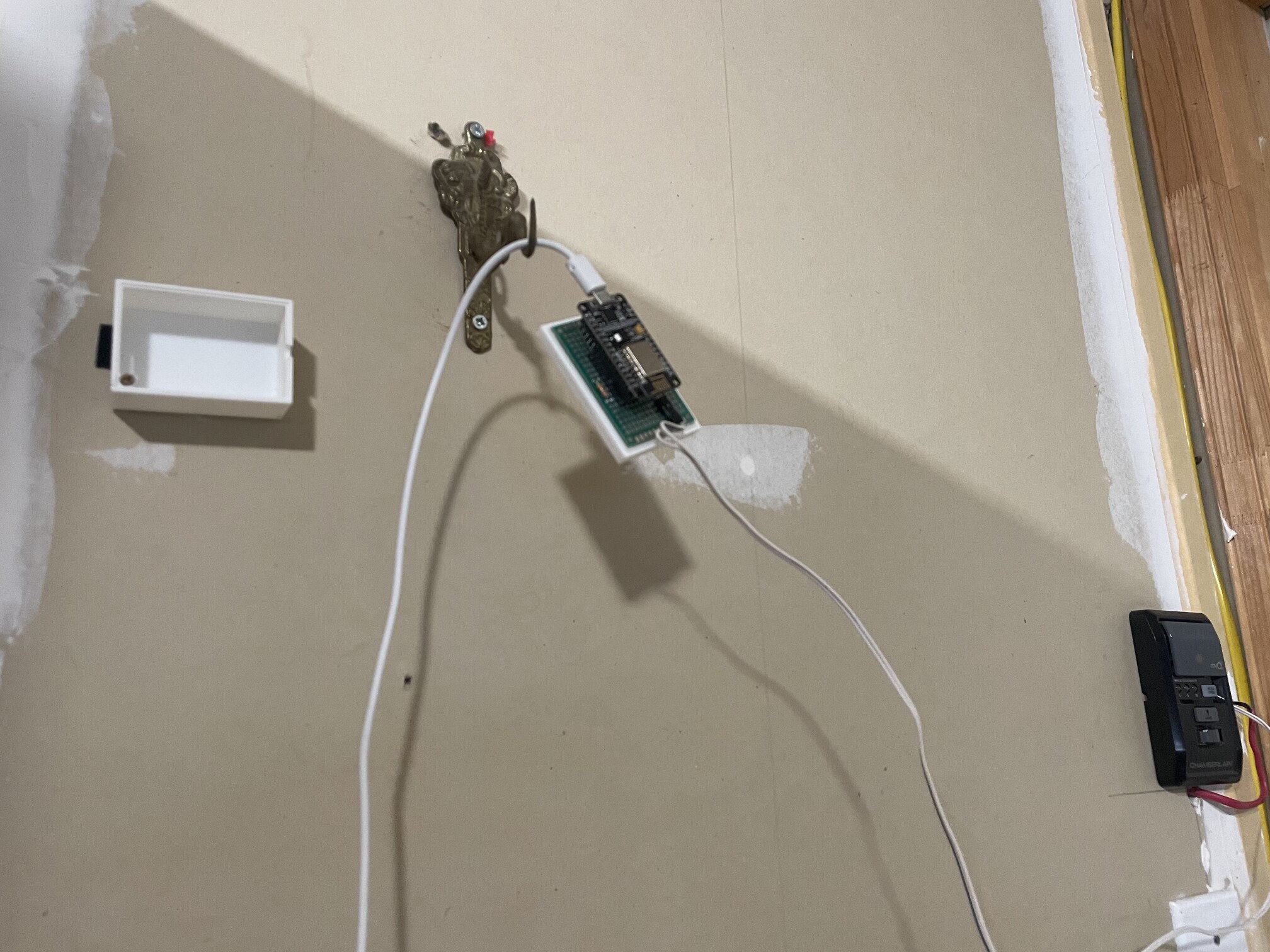
The pinnacle of elegant and refined design.
I have garage door status in Home Assistant!
I’ll probably monitor this for a bit, and see if I can decode some of the other status bits. There might be something else of interest in there. I’m very likely to add transmit functionality at some point, using the aforementioned level-shifting MOSFET. Then, I can have complete control of my garage door from Home Assistant, without any reliance on a third party.
Finally, the last piece of “cloud-connectivity” is gone from my smart-home. Good riddance.