Rain Capture
Background
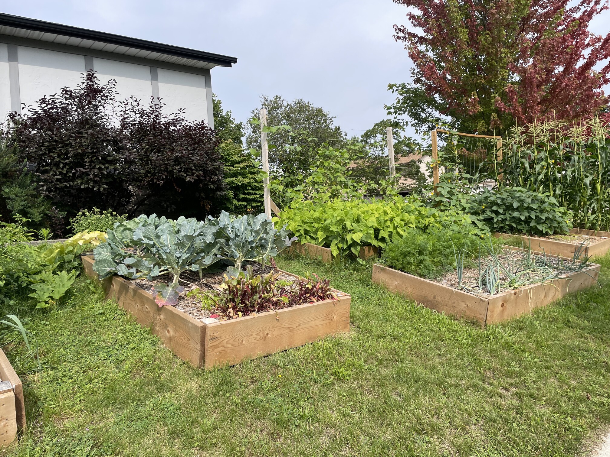
Our garden!
We had a problem back in the summer of 2022. The garden my wife and I planted was dying. We simply didn’t get enough consistent rain through the hot summer months to keep it alive. Most people, when presented with this particular problem, hook up a garden faucet to a sprinkler or irrigation system and call it a day. I wasn’t satisfied with that, because we do get enough rain to keep a garden, it just comes in large storms, separated by weeks of heat.
We had invested a lot of effort into making sure that our garden was self-sustaining - requiring as few external inputs as possible to keep producing food year after year. Using limited groundwater just wasn’t going to be acceptable. Similarly, I didn’t want to have to connect pumps to utility power.
Project Scope
The scope of the project was clear in my mind. For the 2023 growing season, I wanted to:
- Collect the rainwater that fell on our roof.
- Pressurize that rainwater to ~50 PSI to allow running “normal” irrigation techniques.
- Power the whole thing with solar power.
Whenever I take on big personal projects like this, I always try to incorporate some new technology or process that I haven’t used before. I find that hands-on experience is truly the best way to learn new things. My initial designs for this project used hand-built PCBs with ATMega microcontrollers to handle all of the control logic - nothing too fancy. I decided that this project would be a great opportunity to dip into the world of industrial automation - PLCs, Modbus, 4-20mA sensors, high-amperage contactors, etc.
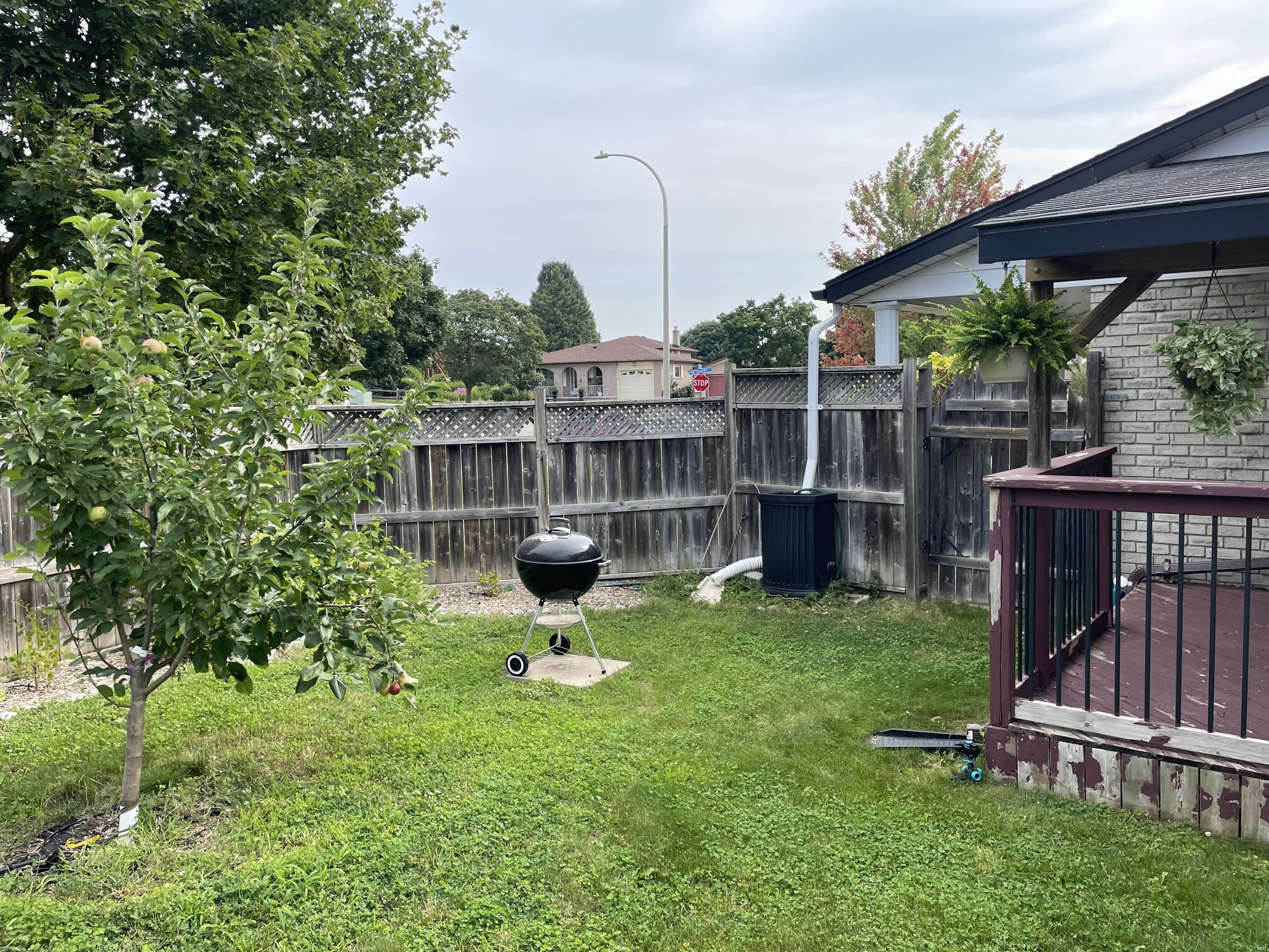
Our backyard looks like this. There isn’t room for large rainwater collection tanks beside the downspout, so water will need to be pumped from a smaller rain barrel into the large collection tanks during rain events.
So here’s what I wound up with. I’ll split the discussion into power, plumbing, and control electronics.
Power
I knew that power was going to come from solar panels, and I began by breaking down the various power consumers to determine a battery and panel size that would suit my needs. This analysis led me to a 12 volt, 100 amp-hour marine deep-cycle battery, and around 100 watts of solar panel. After some searching around, though, I decided to significantly over-size my panel for my needs. The biggest driving factor for this was that I had a large draw that needed to run when it was raining!
A key part of this plan involved pumping rainwater from a rain barrel into larger collection tanks. This pump would, of course, need to run when it’s raining, and thus cloudy out. If I had gone with a panel “adequate” for my system, the battery would be discharging during rainy periods, and eventually I wouldn’t be able to run the pump anymore. I did some math based on the output from the pump. At 750 gallons/hour, and 400 gallons of water storage, the pump would never need to run for more than a couple of hours in total. So even in the worst rain storms, it would only pull a total of 5A X 12V X 2H = 120 watt-hours. Given the battery had 1200 watt-hours available, this wouldn’t be a significant impact - even if it was running in the dead of night!
I still wanted to make sure that I could keep the system topped up if it’s rainy for several days straight, so I decided to purchase a 250 watt solar panel, alongside the aforementioned 12V, 100Ah battery, and a 30 amp solar charge controller from Renogy.
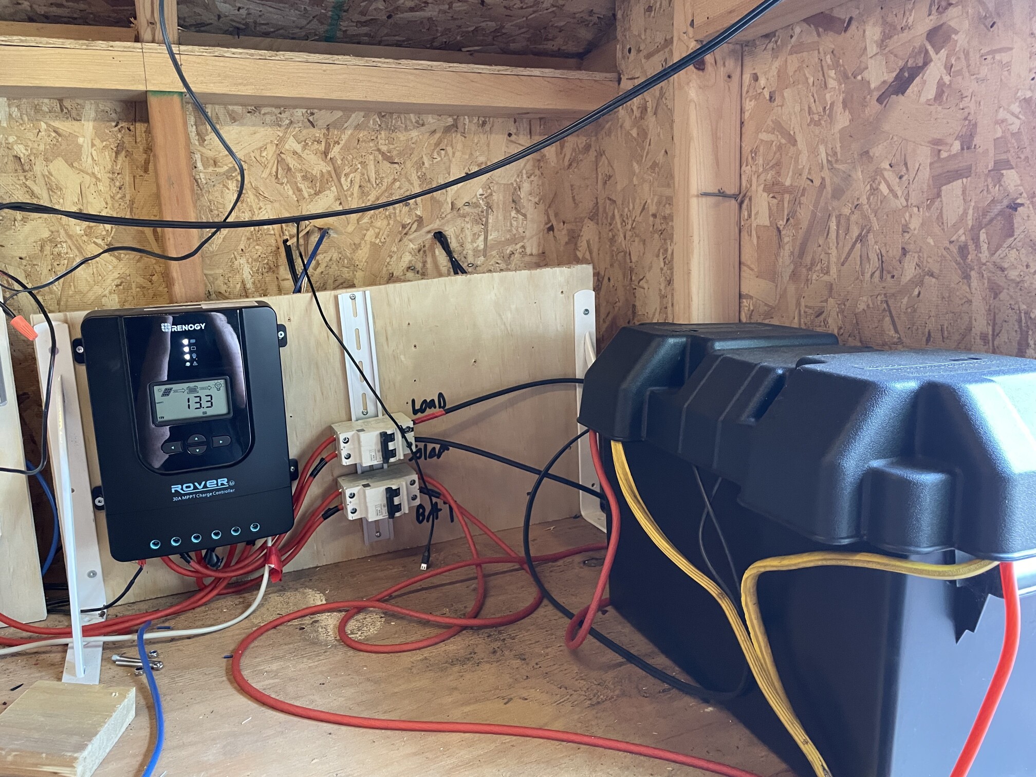
Charge Controller & Battery
This wound up being an excellent decision - even on complete overcast days, the panel will produce 20-25 watts continuously throughout the day. Since the system only consumes around 11 watts at idle, this can keep the battery topped off even if it’s dreary outside for days on end.
To round out the power system, I installed an automotive fuse box, several circuit breakers of varying ratings, a 12V to 24V boost converter, and a 12V to 5V buck converter to power the various accessories.
Plumbing
If we’re going to be moving a bunch of water around, we’re going to need some plumbing!

Plumbing Diagram
The first major purchase for this system was two 1000 litre “IBC” totes. These totes were connected together with some PVC pipe to keep the level between them the same - effectively creating one large 2000L storage tank:
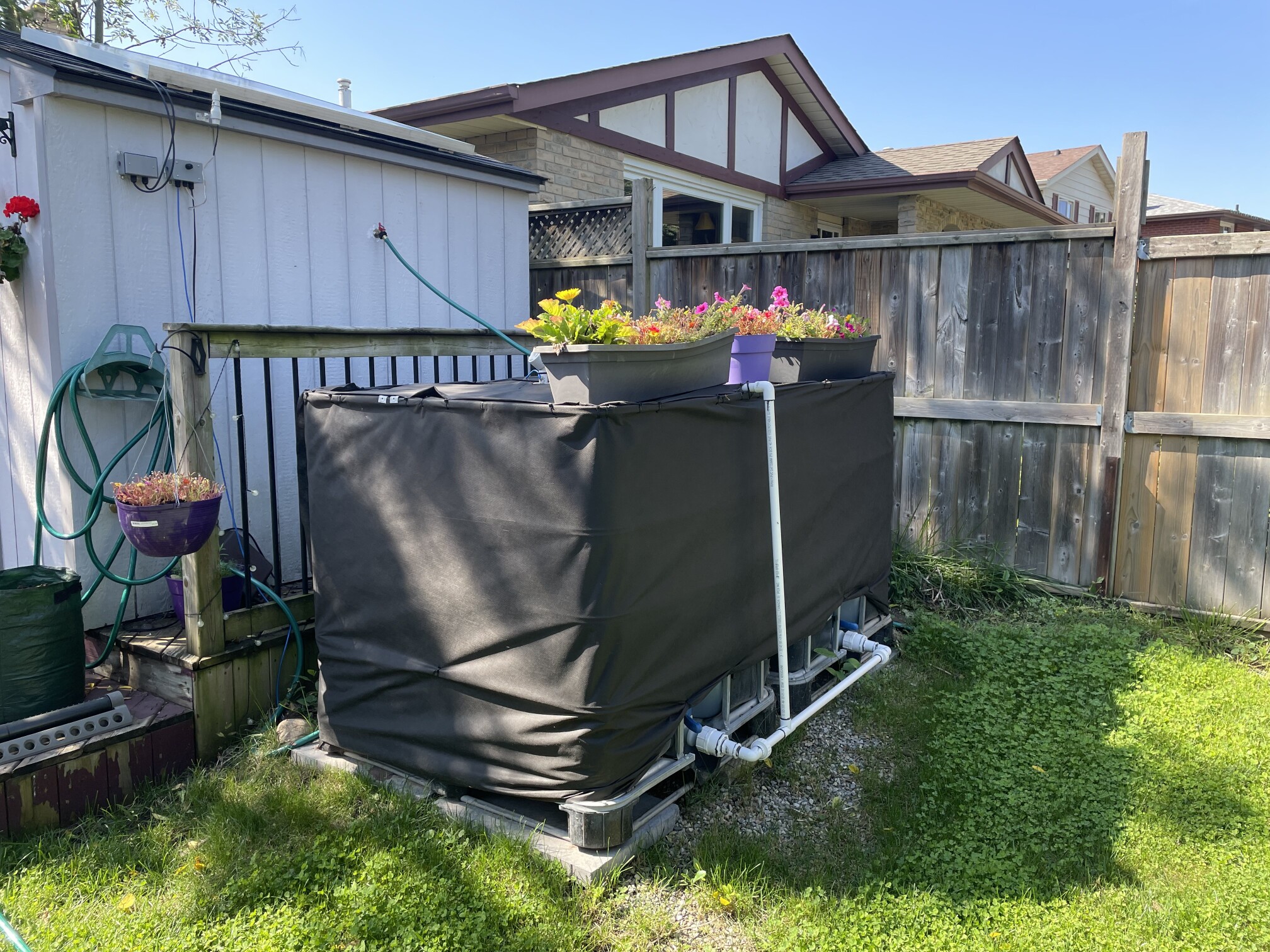
That’s a lot of water.
We can divide the diagram into before and after the large storage tanks.
Before the storage tanks, I have a rain barrel that’s fed from the downspouts off of the side of the house. This is fitted with an automatic bilge pump, raised up on a brick:
Rain barrel fed from downspout
The pump is mounted above the bottom of the barrel to reduce the fine (and not so fine!) particles that it would otherwise pick up. The pump is powered by the control electronics, and can empty the bin in just a few minutes. The output from that pump goes into the collection tanks through a garden hose routed around the edge of the garden.
After the storage tanks, the water goes through several stages before being delivered to the points of consumption:
- Coarse filter - captures asphault shingle bits, bugs, and anything else that might risk puncturing the diaphragm of the pressure pump. This filter is surprisingly clean - I think raising the bilge pump might have been all that was neccessary.
- Pressure pump. This 3.3gpm free flow, 60PSI max head pump is the primary pump for this whole system. It’s a bit of a power hog - at 12V, it can consume upwards of 10A at peak. More on that later.
- Fine filter - captures algae, sand, and other small particles under 10 microns. This filter is used to protect the pressure tank, gauges, and drip irrigation lines from clogs and other contaminants.
- Pressure tank - this tank, much like in a well water system, provides a buffer of pressure to avoid the pump having to run continuously. It allows the system to pressurize to 50psi, then slowly draw down until it reaches 30 psi before the pump kicks back on.
- Pressure gauge - for manual observation, and calibration of the electronic sensor.
- Pressure sensor - this 4-20mA pressure transducer is used to inform the PLC about the current water pressure, used to cycle the pressure pump and maintain safety margin.
- Flow meter - this flow meter provides a pulse for every 100mL of water that flows through it. It’s cheap and inaccurate, but it allows the PLC to detect leaks and measure approximate water consumption.
Note: The water you get on the other side of this is not potable by any stretch. It won’t have “bits” in it thanks to all of the filtering, but bacteria likely thrives in this water, even after chlorine treatment in the storage tanks. I wouldn’t drink it without boiling it first - or ideally, don’t drink it at all!
After all of this, the water is available to two sprinkler valves, and one manual faucet. The sprinkler valves go out to the irrigation systems in the front and back gardens, and the manual faucet is used for hand-watering hanging baskets or any other outdoor water needs around the property.
Control Electronics
Now for the fun part - the brains of the operation!

Electrical Diagram
All of the control logic is powered by a Click Plus PLC from AutomationDirect. This whole project was a bit of an excuse to play with PLCs and other industrial automation equipment and protocols, so even though you could do this with a tiny microcontroller, this worked great. It was also a bit of a relief to have some additional reliability here - a malfunction could cause an awful lot of water to wind up in places it shouldn’t, flooding the yard or garden. Ladder logic may not be fun to create, but it sure is easy to follow!
Click PLCs are so-named because you can “click in” additional I/O modules with very little effort. For this system, I connected a 4-in, 4-out + 2 ADC module, and an additional 4-in, 4-out module. These modules use relays for the output, so can be safely loaded for approximately one amp per output.
The PLC takes a number of inputs, which drive different functionality.
One of the key inputs are float switches:
- Tank low - a float switch that indicates when the tank is at a low level and it’s no longer safe to run the pressure pump for risk of losing prime or running the pump dry.
- Tank high - a float switch that indicates the storage tank is full. When the tank is full, the rain collection pump is disconnected, preventing an overflow.
These switches are wired in a redundant fashion - there are actually two switches for each level indication, wired in series so that if one fails to break the connection, the other will. This helps prevent an overflow or dry-running the pump, even if a float switch fails.
The PLC has a number of other interesting inputs as well:
- Rain sensor - a sensor which detects rainfall using expanding cork discs (available off-the-shelf as an irrigation system component!). The PLC uses this to power the rainwater transfer pump only when it’s raining.
- Water flow meter - this flow meter provides a pulse for every 100mL of water that flows through it. The PLC uses this to guesstimate at water consumption and leak detection.
- Safety stop switch.
- Water Request - used to indicate the hand-watering spigot will be used, and activates the system.
- Pressure sensor - used to understand the current water pressure in the system and trigger the pressure pump to come on and off to maintain the set range.
- Temperature sensor - used to ensure the pump is operating within safe limits.
The outputs of the PLC are hooked up to a few things:
- A simple relay to run the rain collection pump - at only 2A continuous draw (5A peak), a simple power relay can be used here without contact heating concerns.
- A 30A contactor to run the pressure pump. My initial attempt used an automotive relay, but I noticed very quickly that there was significant arcing when trying to break the connection, and the relay (and cabling!) was uncomfortably warm. I blew through several protective fuses which were intended to protect the cabling. I re-wired the pump to instead run through this high-current contactor with 4-gauge copper wire (with appropriate upgrade in circuit protection to a 15A name-brand DC circuit breaker!), and noticed an immediate improvement in the pump’s power (less resistive loss!) and overall heating.
- A simple LED indicator to denote the safety stop as active.
- Two sprinkler valves, which send water to the front and back gardens.
The choice of solar power controller wasn’t an accident or just purchasing the cheapest one - I knew that I wanted to pull data from the controller into my PLC logic in order to drive different functionality and safety systems. The Renogy controller supports Modbus over RS232 - as does the PLC. I made up a special serial cable to connect the two, and was able to pull in power consumption and production statistics into the PLC. The PLC uses this information to protect the battery - if it’s low on charge, it will stop rainwater collection to ensure there’s enough power to make it through the night. It also refuses to run the pressure pump unless the solar panel is producing enough energy to compensate for the power draw.
The other benefit of the PLC was how easy it was to add safety logic with high confidence of it working correctly. More than half of the PLC program is just ensuring various safety constraints are met:
- If water pressure drops when water request is not active and no sprinkler valves are open, trip the safety for a potential leak.
- If water flow exceeds programmed limits while a sprinkler valve is active, trip the safety for a leak.
- If the pressure pump is on for more than 10 minutes straight, or reaches 50 degrees Celsius, trip the safety.
- If the pressure pump is on, and the pressure is not increasing, trip the safety for a potential leak or dry-running pump.
All in all, it looked like this, mounted on a piece of plywood:
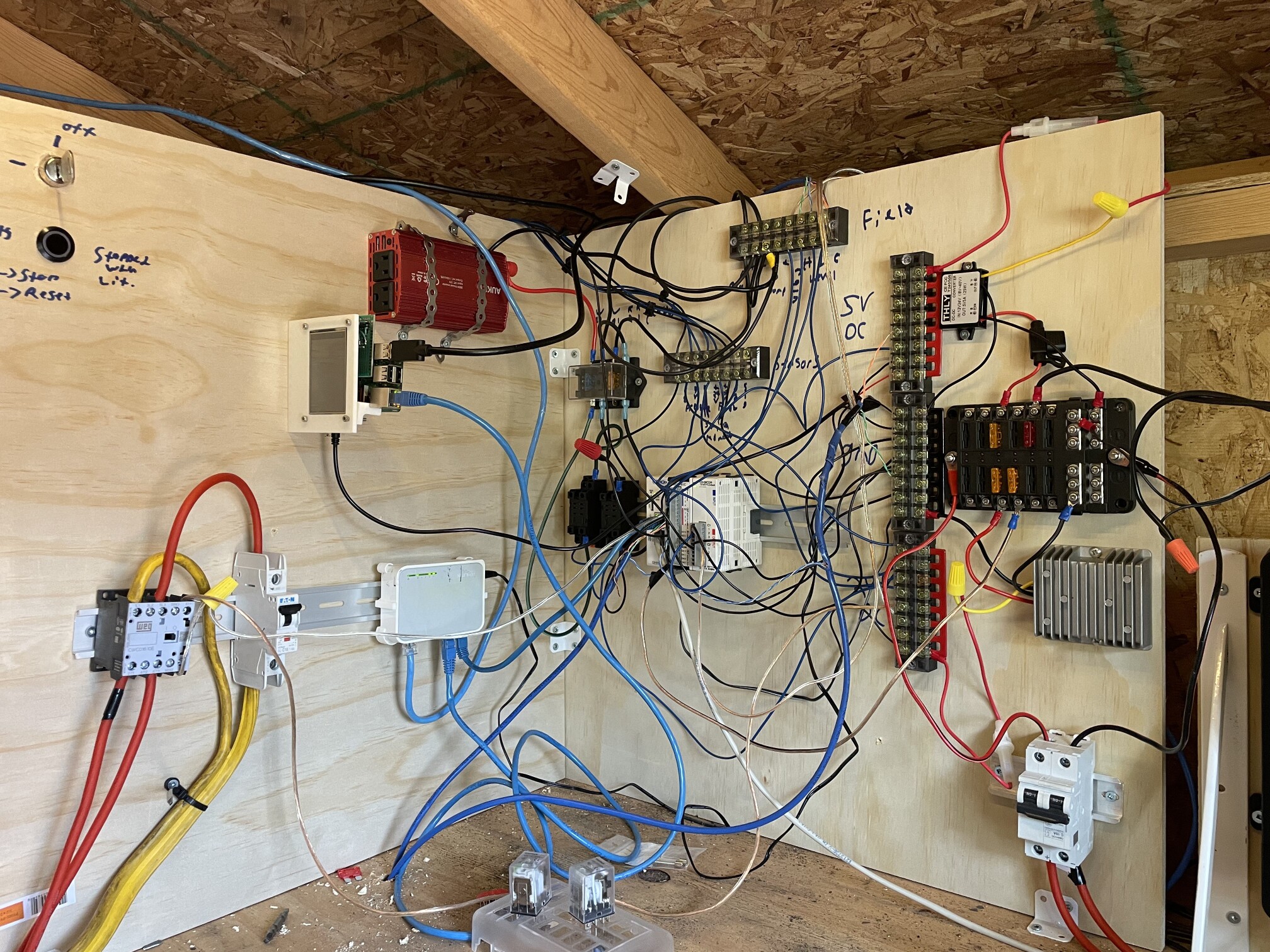
Ew.
In retrospect, I should have spent the $80 or so and purchased a steel enclosure for all of this - it is messy and potentially hazardous as-is. This system has since been disassembled, but if you’re thinking of doing something like this… buy the enclosure.
Irrigation
Why were we playing with PLCs again? Oh. Right. We were supposed to be watering the garden.
To round off the project, I installed drip irrigation tubing in the front and back gardens to provide water to the plants as they need it.
The two irrigation channels are triggered for half-hour increments by a dashboard within Home Assistant as-needed. I haven’t found a need to automate it yet - I’m out in the garden every day, and it’s usually pretty clear if the soil needs water or not!
Summary
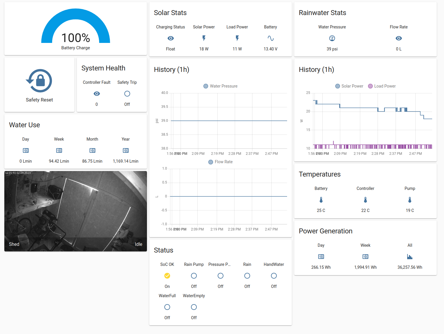
Home Assistant Dashboard
This system has worked marvelously over the 2023 growing season. Our crops have remained watered and happy throughout the summer. A few components failed here and there - usually cheap ones, and I purchased higher-quality replacements. In one case, the hose for one of the irrigation channels burst under pressure. This would have been a disaster, but the safety mechanisims built into the PLC triggered immediately upon noticing a much higher flow rate than expected for that channel, closing the sprinkler valve and preventing a flood.
I was able to get all of the data from the PLC plumbed into Home Assistant by connecting to the PLC’s Modbus TCP server, producing an overview dashboard that lets me keep an eye on the water consumption and solar power stats throughout the day.
Overall, I’m super happy with this project - I got to try out lots of new things, learned a lot, and built something that saves me time and money.
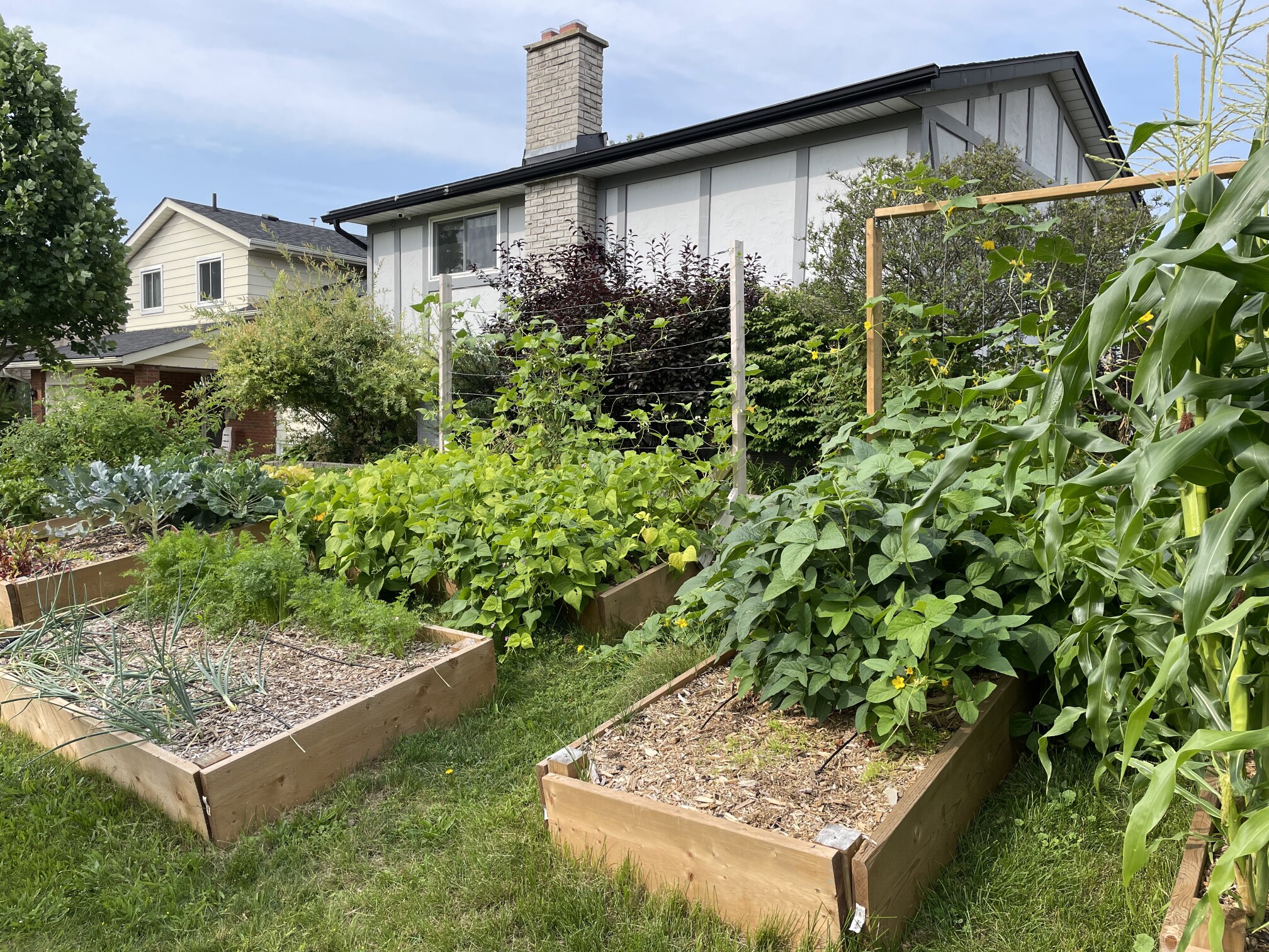
Lush and productive!